I revised the turret based on the most recent information I had. Relying on Alvah Hunter's description, combined with studying the three engineering drawings, plus two artist sketches of the turret interior of Passaic and Montauk, plus some educated guess I arrived at the following turret roof configuration. All the parts were laser cut. None of the references were entirely consistent, so I had to make some decisions. The turret frames are 1/8th inch plywood. The simulated iron rails and the wood grating are laser cut 1/32nd inch plywood. The perforated iron plate is laser cut resin impregnated backer board.
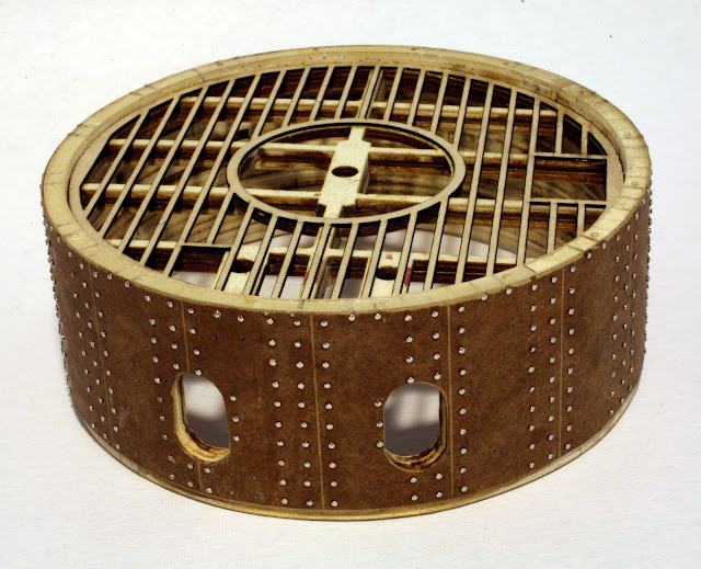 |
| 512 Rivets, each made from a sewing pin, individually trimmed to size and inserted in a drilled hole. Whew! And there are more to go! |
 |
| The turret on its base with the pilot house added. Still lots of detail work to go. The circular hole is for the smoke box vent. |
The photo below demonstrates how the turret will be removable to allow one to view the guns and other to be added details. I haven't decided if I want to make the pilot house removable, as it is needed to support the to be built awning. The two holes are for the bottom axles of the armored port hole stoppers. One will be inside the smoke box and not very visible.
 |
| The turret will be removable to allow viewing of the guns and interior. |
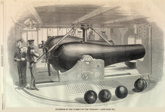
I have consolidated several drawings of the turret interior that I found on the web below for ease of comparison. I annotated some to note discrepancies or other items of interest.
 |
| This drawing shows the best view of the smoke box. Note the quilting on the walls and the perforated iron on the roof. There is no visible ladder to the pilot house in any of these drawings but text descriptions describe a hatch. The ladder was probably removable. Note how the XV inch gun is on different sides of the turret in the various drawings. |
 |
This view shows gratings leading to the turret chamber below the turret. Note the thin ladder in the background, compared to the stairs in the Montauk drawing. Hunter describes a removable iron ladder. There is no smoke box on this drawing. Both drawings show a bolted ring under the pilot house.
|
 |
| A good engineering drawing showing the port hole stoppers (that are different sizes) and the smoke box. |
 |
No smoke box in this drawing. Did the Passaic have one or was that a latter addition? Hunter describes how the smoke box was not particularly effective and was damaged by the blast from firing the gun.
|
Here are some questions people have asked about the turret and my answers based on my research.
-The engineering drawings show the stack and the vent hole from the stack, but as the turret traverses, it would seem that the stack would be venting into the turret unless the alignment is perfect. How's that work?
The pilot house was fixed to the hull. The rest of the turret rotated as a single unit. It was actually hydraulically lifted a couple inches to rotate. The turret was supposed to be sealed at the turret-hull base, but the seal leaked, so they caulked the turret when they went to sea. The rails and perforated plate were held in place only by gravity. Hunter describes an accident where the plates were knocked loose by an explosion. The iron ladder that was stored on the turret top was blown over board and not recovered in the incident.
The turret had wrought iron plates covering the rivets, an early form of spall liner that is currently used on armored vehicles. These prevented incoming shot from sending sheared-off rivets flying around the interior of the turret. However, a pilot was killed in the battle for Charleston when a shell sent a rivet flying in the pilot house, which apparently was not so equipped.
-How'd they ventilate the turret when firing the guns? [And can you imagine the noise in that small, all-metal space? --WOW!]
There were two blowers in the hull under the turret, in a space they called the turret chamber. These blowers drew air through the ship and out the turret. The hull was water tight during sea movement. They actually sealed the hatches and caulked them as the installed rubber gaskets were ineffective. Later they added hatch and ventilator combings that allowed better air flow through the ship.
The XV inch gun actually fired with the muzzle in the turret. It had to be LOUD!
-How'd they get into the turret from the deck? And for that matter, how'd they load food, powder, shot and so on?
There were removable ladders from the turret chamber into the turret and from the turret to the turret roof. There was a ladder on the external side the turret. When underway or in battle to exit the ship you had to go from the hull to the turret chamber, up a ladder into the turret, up another ladder to the roof and then down the external ladder. They used the turret roof as a quarter deck when underway, as the deck was awash.
There were other hatches on the hull deck for loading supplies and ammunition. The ship had a steam condenser to make fresh water.


I love how you don't do anything half way. That's some top notch quality work there! I look forward to watching this progress.
ReplyDeleteI commented earlier but apparently my comment did not go thru the network without getting dismembered ... so here is an abstract: Great work on the models, Bern! I learned a lot from your posts about the monitor, particularly the turret and gun info. As the owner of the website BigBadBattleships.com ( http://BigBadBattleships.com/ ), a picture history of the ironclad battleship, I would like to republish some of your content in my Civil War section and Gunnery Dept, with attribution of course. Specifically, I would like to reuse the picture of the turret roof components and the MONTAUK turret interior. I'd also like to link to the relevant sections of your blog and to republish, in part, Eugene Canfield's discussion of the dual gun sizes. The pictures would be used on our USS MONITOR, URAGAN class (10 copies of the PASSAICs built by the Russian navy, originally armed with Russian-made Dahlgren copies), and Early Turretship pages (the last accessible through our Gunnery Dept. submenu). Thanks for your dedicated research and modeling work -- and for sharing through your outstanding blog.
ReplyDelete-- LT CDR Percival Poppycock, OPS, KCIE
LT CDR Poppycock,
ReplyDeletePlease go ahead with your plan to republish. I checked out your site and it is full of good info. Please be advised that the way I constructed the turret roof may not be entirely accurate as the info I have is not complete and in some cases conflicting. Please let me know when you publish the material as I will do a blog post advertising the link on this blog.