A journal following the history, design, construction and operation of Bernard Kempinski's O Scale model railroad depicting the U. S. Military Railroad (USMRR) Aquia-Falmouth line in 1863, and other model railroad projects.
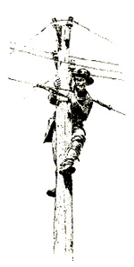
One of the key technologies from the civil war was the telegraph, both for transmitting military orders and for control of the railroad. I had hoped to add a telegraph system to my layout to add even more authenticity. There is another modeler across the river in Maryland that uses telegraphs for train orders and OS reporting on his layout. So it is a feasible aspect, but I know almost nothing about it.
Tonight I got an interesting telephone call from Walt Mathers asking me if I would be interested in participating with the Morse Telegraph Club in the 150th reenactment of the first telegraph message from a field army to Washington, DC. They need some high ranking officers to gather at the War Department to receive the first message from General McCellan's command. While I am not a serious re-enactor, this sounded like a fun event and a good opportunity to learn more about how telegraphs were used in the civil war. So I am probably going to do it. Here is a link to an affiliated group with information on civil war re-enactors doing Morse Code
Telegraph station at Stonemans Station used an old conductor's car as a shed.
I have been looking at some ideas to expand the Aquia Landing area of the layout. The objective is to better model this busy harbor. I am concerned that the current design is just too cramped. After looking at possible options (see earlier track plans posted here and here), I think the attached plan captures several key features of the prototype location, such as the wye, two piers, room for several large ships and space for some of the many structures that the USMRR built.
This expansion will require remodeling some of the existing walls. I am exploring the cost and feasibility of this. I had a general contractor look at it tonight and he believes there are no technical issues, such as HVAC or structural.
The large space to the right is the HDTV room. The opening in the wall at the bottom is the door to my home office.
The EasyDCC system has a command module that includes a nice control panel. You need to access this panel to program decoders. At first I considered installing it below the benchwork, since the high tech electronic design did not fit my 19th century esthetic. But the need to program the sound decoders lead me to opt for usability over esthetics. So I installed the command module on the fascia at the far end of the layout. This will hopefully allow good radio signal coverage. It is where I have the wireless transceiver now.
I cut the appropriate size hole in the fascia with the saber saw. I had to reinforce the benchwork holding the fascia as some of the supports were cut away in this process.
I built a shelf for the programming track. The shelf is 18 inches long and 3 inches wide. The track is a section of Atlas code 125 flex track, unweathered and with electrical leads soldered to the bottom
of the rails. The hidden wires go through the fascia and into the command module.
Most decoder functions can be programmed on the mainline, but the EasyDCC recommends using the programming track for initially setting decoder address. So it will probably be rarely used as a programming track. When not used as a programming track, operators can use the shelf to hold paper work, or other small items.
Because I was concerned that a loco could fall off the shelf due to clumsiness or other calamity, I added a 0.22 inch think laser cut acrylic protective panel along the front edge.
Now I just have to make sure I don't get scenery materials or paint in the module.
Today's mail delivered a package from Tony's Train Exchange with a QSI Revolution U sound decoder and three different speakers. I selected the QSI decoder because of its higher current capacity rating compared to the Soundtraxx decoders. The three speakers are different sizes ranging from 0.75 to 1.06 inches because I didn't know which ones would fit. I ended up using the biggest speaker, the QSI High Bass 1.06 speaker with its snap-on enclosure. This speaker barely fit in the firebox. I had to use my motor tool to trim one of the walls of the firebox so that the fit wouldn't be too snug. I was concerned that if the speaker driver cone was too tight, the bass frequencies would be degraded.
Before installing the decoder, I tested the engine. The lead driver on the engineer's side was showing a short with a resistance of 130 Kilo ohms. The back driver was not shorting. This would cause a current leak of about 1 mili-amp at 12 volts, about what you might see if I were to use resistors on the wheel sets for track occupancy detection. I tested the loco on the tracks and the short did not affect operations. Nonetheless, I tried to find the source and could not. I have no idea what could be causing the problem. I ended up disassembling the loco in the failed attempt to debug it as you can see in the first photo. I even disconnected the drive rods to see if they were the problem.
I added pickups on the tender. In the process I accidentally popped the drive shaft from the universal joint between the motor and one of the gear towers. That was a royal pain to get back installed. I basically had to disassemble the motor from the tender to get enough slack to pop the shaft back in place. Once I had everything back in order and the motor leads picking on both sides of the tender, I tested the tender by itself on analog (DC) power and it ran without the engine. That was good.
As I did in the other locomotive, I disconnected the wire from the pilot truck as it was causing trouble with binding. While I had the pilot truck off, I added the same number of paper washers as I did to the Haupt to raise the nose of the engine to provide clearance for the pilot truck. I also added the insulating ring on the front of the cylinder just in case.
With the decoder and speaker in the boiler and the motor in the tender, as well as all wheel pick-up on the tender, I had to make two wire harnesses. One to bring track power from the tender to the decoder. Then another to send DCC regulated power back to the motor. I used the second plug that comes with the loco lighting wires to make the return wire harness to the motor. It was an easy task to disassemble the micro-plugs and reassemble them with the wires I needed. I used heat shrink insulation to protect all electrical joints. Thus the loco now has two plugs between the tender and the engine.
One curious aspect of these locos is that the frame is hot on the engineer side on the tender, but is reversed for the engine. That is, the frame is connected to the fireman's side on the engine and to the engineer side on the tender. Once I figured that out, installing the decoder was fairly straight forward. I tested it before shoving everything into the boiler. It worked! I was very happy.
A photo of the installation
Then disaster. As I shoved everything in the engine, the wires to the decoder broke at the plug-in harness at the decoder. The tight fit of the speaker but too much tension on the wires and they broke. There was no way to re-solder the leads back to the plug as the joint is encased in the plastic plug and is a very tight package. Arrrrrgg!
I examined the wires. Only the red and black decoder leads broke. I decided to remove the plug and solder the leads direct to the board.
Bad move! The plug was not a friction fit, but actually hard soldered in place. I could not tell this from the outside because the solder joints were under the plug. It must have been assembled in a wave solder machine because you can not possibly get a soldering iron under the plug. In the process of removing the plug I damaged the printed circuit pads on the board. The pads for the head light leads were gone, but enough of the pads for the other wires were present. This allowed me to painstakingly re-solder the decoder leads directly to the board. It wasn't easy, but I got it to work. I had to use the F5 lead (number boards) to provide a signal to the headlight because the white wire pad for the headlight was totally gone. That explains why it flickers in the video. Hopefully I can adjust that with a CV value. I tired a 220 ohm resistor to drop the light brightness, but that made it too dim. So the light is running straight off the decoder leads with no drop down resistor.
Once I got everything back together, I tested it and it worked. I was both amazed and pleased, as I thought that I had ruined this decoder.
The following video shows a quick test of the loco as it rounds the tight curve behind the engine terminal at Falmouth. The speaker sounds pretty good. Now I need to read the various manuals to customize the sound of the engine. The air pumps must go, but the whistle is very good.
I think you'll agree - the sound adds a whole new level of life to the layout.
With all the disassembly I have done on these locos now, I am beginning to understand how they work. This is making me more confident that I will be able to scratch build my own locos when the time comes. I would like to build a yard engine with link and pin couplers on both ends. I'd also like to try building some of the engines that ran on the USMRR in Alexandria, such as the Devereaux and the Virginia. They would go nicely with the planned model of the Alexandria roundhouse I want to do too.
In looking at photos of many wooden trestles from the Civil War I have concluded the majority were built in the usual manner with the vertical posts under the rail stringers( See photo below). However, Haupt, in his book Military Bridges, expounds the virtues of the "W" trestle (see my earlier post here). Yet, I had a hard time finding examples of Haupt's design in practice.
A USMRR trestle on the City point line built with
the usual design of vertical posts under the rail stringers.
In looking at photos from the Chatanooga area I finally spotted a couple of decent photos showing this type of trestle. The two photos below were taken on two different trestles on the Tennessee and Alabama Railroad in Maury County, TN. The USMRR rebuilt these bridges after the Confederates burned the originals.
Both bridges show similar construction techniques. They use finished lumber instead of raw logs. The ties are relatively thin boards and not normal thickness ties.
The bridges include a curious feature- sections of timber under the stringers where piers rest. The timber sections do not form a complete stringer and I wonder what purpose they serve. Since they appear on both bridges, I assume they are intentional design items and not field changes perhaps added to raise the grade to allow standard bents to be used in a slightly deeper location. These extra pieces are not included in Haupt's drawing.
With all the variation in field installations, following a standard drawing is probably not the best way to get an accurate model. Ideally a modeler would follow a prototype example when building a model trestle. If you pick a spot where no photo documentation exists, like I did at Clairborne trestle, then following the standard drawing is a reasonable fall back approach, but just about anything could be possible.
The Culleaoka Trestle. Note the details in the lower left showing the piers and bracing at the ground. Also
note that the piers are finished lumber and not raw logs. In spite of Haupt's text, this trestle
has X bracing on most of the visible bents.
The Harris Trestle shows similar construction details as the Culleaoka Trestle above. This bridge is
closer to Haupt's drawing, but it has the curious cut timbers between the
piers and stringers.
The Hanover Branch Railroad facilities at Hanover Junction before the Civil War era were rather extensive. A hotel built by the railroad housed railroad office facilities. There was also a turntable, an ash pit, and various smaller buildings used for railroad activities. However, the Gettysburg Campaign of the Civil War brought Rebel soldiers to the area who were responsible for destruction by fire of the wooden bridge and all railroad facilities except the hotel building.
The Hanover Junction Valley Junction rails were removed during the period 1928 34, bringing the end of service to an area that was highly dependent on the railroad. And this was the "Hanover Branch Railroad."
I built a tool shed structure for Falmouth. This structure is based on a building at City Point, VA as I don't have any photos of the actual facility at Falmouth.
The structure is a laser cut core from 1/8th inch plywood with Mt Albert Board and Batten siding applied. The window and door are Tichy parts. The roof beams, rafters, purlins and joists are strip wood, but I didn't detail them because they can not be seen.
I originally was going to add battens to the roof, but the photos at City Point show a double layered type roof using overlapping planks and not battens. I may retrofit another set of planks over these to simulate that, but I like the look of this roof. The chimney is a piece of brass tube with a small section soldered on top to make a smoke jack.
Initially I had planned to put the tool shed between the back storage track and mainline curve. The idea was that the building would hide some of the sharp curve. The problem was that the building just barely fit in that spot. Furthermore, that spot is where a safety track for the turntable lead would reside. The safety track would be a short section of track that would prevent engines that overshoot the turntable from going in the pit.
So I decided to move the building to the location shown in the photo. In this spot the building still provides a view block function, but it looks like a more balanced composition. I had to shorten one of the storage tracks to make room for it. Instead of engines, this track will be used to store spare wheel sets and trucks. General Haupt is standing at the site of the new safety track. I still plan a few more smaller sheds and lots of details for this area, but it is coming along.
Having extensively dissected my Haupt locomotive this weekend I am now much more familiar with the internal wiring. It is really quite simple. To install a decoder will be a simple matter of swapping out the existing harness but leaving the chassis connections intact.
I think the optimal solution for sound is to install the decoder in the boiler with one speaker. Potential speaker locations include the stack or the fire box. The info sheet at this web site suggests not venting the speaker through the stack, as upward sound propagation of front wave does work as well. So the firebox location might be better. It is also a large internal volume allowing a bigger speaker. This tech note is quite interesting and worth reading.
The internal wiring in the boiler is easy to reroute. Currently there is one 2-pin plug from the tender to the engine. I would replace this with a 4-pin plug to carry track power to the decoder and then motor power back to the tender for the motor. But I have some questions that perhaps a reader can help answer.
1. What decoder to use? The boiler tube on the Haupt measures 0.96 inches ID. The QSI decoder Rev-U decoder measures 2.13 by 0.69, so it should fit. The current rating for the QSI Rev-U is 2+ amps stall and 1.3 Amp continuous. What is not clear to me from the QSI website is how the sound will be. They don't seem to have as extensive a variety as Soundtraxx.
2. Dave Schneider at SMR advises against the Soundtrax decoders because they might not handle the current rating, but Mitch Oldham did a test on my McCallum and it showed stall current less than that. Will current draw be an issue if I go with Soundtraxx? The light steam Soundtraxx decoder would be a good fit.
In reading the Easy DCC manual. I learned that you can control the various sounds from the decoder. So having inappropriate sounds such as an air pump or steam blower is not a big concern, as you can turn them off with the appropriate Control Variable (CV).
3. Connector plugs? Miniatronics makes a nice 4 pin plug, (Photo at the right) but their website says the current limit is only 1 Amp. These appear to be the same type of plugs that SMR uses on their locos, so I wonder if that will be a problem.
4. A 0.75 inch speaker will fit in the boiler, while a small oval speaker might work in the firebox, which is essentially a empty box about 0.75 inches wide and 1.7 inches tall. The round speaker would make using the boiler as a resonant cavity easier. According to the tech report mentioned above, a bigger resonant cavity is better and brass boiler tubes make could cavities as they have still walls, but don't absorb sound energy like die cast metal. Plastic resonant cavities are less effective as they vibrate too much.On the other hand, folks are reporting good results with QSI High Bass aluminum cone speakers, but the smallest is 1.06 inches in diameter and too big for the boiler, but it might fit in the fire box if it fired sideways.
I have been ignoring the DCC technology for the past couple years while I focused on the technology of the 19th century, so I am a bit out of date. There sure are a lot of new products to consider. I don't have a lot of experience in doing this, so I welcome your comments.
Whew, all this electronics talk has me exhausted. I think I'll go build a structure or something.
Well not totally, but it is completed in the main layout room. With the additional of the auto-reverse control unit for the turntable, and laying and wiring the final tracks in the Falmouth engine terminal, all track and wiring is done in the main room. I still have to lay track and wire the Aquia Landing area, but the rest of the layout is operational.
The auto-reverse unit and its bracket.
The first two photos at left show the auto-reverse unit and the wiper mechanism I used to power the turntable. The auto-reverse unit is an On Guard auto-reverser unit from Tony's Train Exchange. I bought several years ago. Unlike the Frog Juicers, this unit will reverse polarity for both rails. Like the Frog Juicer, this unit does not require a separate power supply. Just connect the DCC bus lines to one terminal and the track feeders to the other. It has provisions for a LED output, but I opted to not connect it as the unit is under the bench work and the whole idea is to make the operation transparent to the user.
The On Guard unit is now obsolete as it can't handle the current demands of numerous simultaneous sound decoders. For now it is working as I only have one non-sound decoder on the layout. We'll have to see if multiple sound decoders cause it to malfunction. My layout even at its peak will be a light density operation with at most 5 locos running at the same time. According to information at Tony's Train Exchange web page, this unit should be OK under these conditions, but I won't know for sure until I actually test it.
If I run into problems I can add additional boosters. Having more than one booster is a good idea in general because it isolates the layout into electrical sections. These sections are not like the traditional electrical blocks where you have to manually control the throttle connected to each block. The booster sections are transparent to the operator. All they do is help limit current flow in each booster by spreading the load across multiple boosters. More importantly, they prevent a single short from taking down the whole layout. So for example, if an operator at Aquia Landing causes a short, an operator at Falmouth on a different booster would not be affected.
I have wired my layout into three separate power districts. So typically I will see a max of perhaps three locos operating in any one district. But for now I am running the whole layout on a single booster. I will need to purchase additional boosters at a later point.
The bracket is scrap wood, so please ignore the black
writing as it doesn't pertain to this application.
The third photo shows how the electrical wipers rub against the metal bands on the turntable shaft creating a home-made commutator. The design will allow the turntable to be removed for maintenance or scenery installation. The wipers are twin sections of 0.032 inch phosphor bronze soldered to a brass plate.
The two white wires are frog feeders for the double slip switch at Falmouth. Those feeders must run the full length of the room to reach the Frog Juicer circuits.
I decided to add wipers to the tender of the Haupt to improve its pickup. It was running pretty well without them, but I want to see how much of a difference all wheel pick-up on the tender would make.
First I installed an insulating tab on the bolster beam of the tender trucks. The tender trucks are hot, so without insulation the new pickups would short.
Then I fabricated electrical wipers. At first I tried using 0.010 inch flat brass stock. But these did not work well as the wheels have a fair amount of lateral play, and the brass did not have enough flexibility to maintain contact with the backs of the wheels. So I modified the tabs by cutting off the brass extensions, and soldering on 0.010 inch phosphor bronze wire wipers. I arranged these to wipe on the surface of the wheel. They are flexible enough to track the wheels as they move laterally. I applied a liberal amount of 5 minute epoxy to hold the tabs and wipers in place.
I had to drill two holes in the tender frame to run the wires from the new wipers to the motor lead. I cut the existing red wire to the decoder and soldered in the new feeders, covering the joint it with heat-shrink insulation. I actually did this before adding the wipers.
I tested the connections and they worked. The tender will now run without the engine attached.
With the engine attached it runs nearly flawlessly. It takes a fair amount of dirty track to stall it.
So with the engine reassembled. I did some test running. I ran a train from Aquia to Falmouth, reversed on the turntable and then back to Potomac Run to drop off a flat car of lumber. Everything worked, so I can declare the layout operational.
Overall view of the tracks at the engine terminal at Falmouth
I asked this question last week and got a couple replies that indicated ash pits were not common in the early rail era. I did a little digging and John White in his book "American Locomotives: An Engineering History 1830-1880" has a possible explanation on why.
Grates were a simple, trouble-free mechanism in the days of wood-burning. Cast-iron bars, often T- or V-shaped, answered construction needs very well. Each bar was about five-eighths of an inch thick, four inches deep, and as long as the firebox required. The bars were set about one inch apart. Because the wood was all but entirely consumed in burning, rocking grates were not required. The small amount of ash that was not thrown out through the stack filtered through the grate bars to the ashpan.
Coal presented many more problems and required a more elaborate grate. It produced a hotter fire, and cast-iron bars burned out quickly.
So what happened to the small amount of ash produced? Probably dropped on the ground and shoveled up or blown by the wind.
White's book on locomotives is an essential reference for early steam locomotives. It's not an easy read, but contains an exhaustive amount of information.
I wired up the last three turnouts at Brook using a second Hex Frog Juicer. These were the last frogs that needed to be wired in the main room. So I decided to test them. I fired up the Haupt, the only engine I have right now that has a decoder. It has been a good runner. But in today's test, it would not run well at all. It was stalling and shorting in places where it ran well earlier. The shorts seemed to be coming from the front truck. So started several hours of debugging, but in the end I think I found the problem. I'll provide some more detail in case you run into similar problems on your locos.
The wheels on the engineer side of the Haupt are electrically connected to frame. The wheels on the fireman side are insulated at the hub. There are no wipers on the fireman side of the drivers. There is a single wiper on the pilot truck to pick up power from one axle. The whole frame is hot. If the pilot wheels or drivers on the fireman side touch the frame, there can be a short.
The pilot truck has an oblong curved slot in the top sheet between the truck frames (this is a part on the model only. The prototype doesn't have this piece as its front suspension is much more complicated). Through this slot goes a special stud type screw that attaches to the bottom of the boiler. The screw holds the pilot truck on the loco, but the truck hangs somewhat loosely. There is a cylindrical brass spacer and a spring to provide a bit of suspension. The first problem I noted was that this spring was partially stuck in the oblong slot and not fully engaged. I made washers out of 0.022 inch resin impregnated paper to give the spring a place to rest and to prevent it from getting stuck in the slot. I also added three washers at the top of the spring to help the front of the loco to ride a bit higher providing clearance for the wheels. This also seemed to help the tracking of the truck but it did not solve the shorts.
I tried running the loco, but still was getting shorts. I removed the front truck and the loco ran without problems.
I put the front truck back on, turned the room lights out and tried running. I got shorts and could see sparks. I removed the loco and carefully inspected it. I found scorch marks in two locations, both on the fireman's side. One was on the front of the fireman's side cylinder where the wheel sometimes rubs on curves. The other location was on the bottom of the cross head guides. See the photos.
It appears that as I ran the loco the paint in these locations wore off. Where the fireman wheels touched the bare frame, shorts happened and created arcs. The crosshead needs to be lubricated as friction here will prevent the drivers from turning as it moves down the track.
Using the laser I cut a paper insulating ring for the front of the cylinder. It's the white ring in the photo. I added insulating strips on the crosshead guides (see the first loco photo). I also painted the back plate of the crosshead in case that touched the wheels. I only had to do these fixes to the fireman side as the engineers side is all hot and rubbing doesn't cause a short.
I also removed the wiper on the pilot truck because it started smoking during one of the shorts. The wiper is held in place with an insulated plastic sleeve that prevents the screw from touching the metal (and hot) frame of the pilot truck. I think that this sleeve was compromised when I removed the wiper. It doesn't seem to hurt the loco's running.
After I reassembled the loco, the head light doesn't work. I didn't try fixing that, as I will need to rewire it for DCC when I get a sound decoder for the loco. I'm not sure if the bulb is burnt out or the cut wiring to the pilot truck is the cause. It is actually fairly easy to replace the head light. The smoke box door pops off and the light bulb is a slight friction fit in the headlight housing.
I have not added the wipers on the tender for the engineer's side. The McCallum has wipers on both sides of the tender. Thus the tender will run by itself. The Haupt's tender will not run on its own as it relies on engineer side pickup from the engine.
All three of my Mason locos have had problems with the front truck. It seems like a better suspension might help with the tracking. Slightly smaller wheel flanges and insulating the cylinders may also help prevent the shorts.
Finally, with the engine reassembled, I did some test running and it is working nicely now. The frog juicers work flawlessly. If only all model railroad wiring and track was so easy. Duncan McCree at Tam Valley Depot really has created a great product with these circuits. On the other hand, the locos are beautiful, but temperamental little beasts. Kind of like a.......
I ballasted the area around the wood rick before gluing it in place to make it easier to get an even ground cover.
I built a simple wood rick for the Falmouth engine terminal. What is a rick anyway? The Apple dictionary says,
a stack of hay, corn, straw, or similar material, esp. one built into a regular shape and thatched.
• a pile of firewood somewhat smaller than a cord.
• aset of shelving for storing barrels.
ORIGIN Old English hrēac, of Germanic origin; related to Dutch rook.
Anyway, my model is a open platform design made with strip wood. I situated it between the turntable lead and a storage track. The photos show a flat car in the process of being unloaded. The loaded wood car is spotted on the turntable lead as there is no way to use the loco to spot a wood car on the storage track. In the prototype, the crews could use ropes and poles to switch a car off the turntable and on to the storage track. Or they would assign 50 men to quickly unload it while the engines waited. My operators may have to 0-5-0 it into place on the storage track.
The model firewood logs are twigs from the backyard that I cut and split when green, and set aside to dry. Just like real firewood :) I used Crepe Myrtle and Azalea twigs.
Now where to site the ash pit? The most logical place is on the turntable lead. Perhaps near the water tank just in case some ashes flare up?
Speaking of water tanks, how do you think the water tank got filled? Bucket Brigade from Clairborne Creek that is just a 100 yards or so away? Or did they use pumps? I did find a message from the Virginia Central that mentioned a water tank and pumps were destroyed at a station by Union cavalry raiders in 1862. Can I assume that they used pumps to fill water tanks when artesian wells or creeks were not available?
The turntable structure is complete with the final details added. I started to install the storage tracks that are served by the turntable. I considered adding an engine house, but the overall area is too small and even a single stall engine house was too big. This is probably not a bad thing, as I think it unlikely that they would have built an extensive shop at the south end of the line. Still, I do plan to add a tool shed. The engine shed will be installed at Aquia Landing.
The completed turntable. The pit still needs to be finished.
Staining the staves
I built a single water tank as part of the engine terminal. I modified a design from City Point, where the tank is tapered and the top open. This was a fun project that took an afternoon and evening.
The tapered tanks takes shape
I laser cut the staves so that each one had a .005 inch taper on each side. This was sufficient to allow the staves to line up on the tank with the proper taper. The diameter of the upper tank is 0.25 inches less than the bottom. I laser cut these with a central support to keep everything centered and square.
Trying to keep the deck square to the beams.
I built up the deck board by board on 0.25 inch square and 3/16th inch by 3/8th inch timbers.
The rings are 0.010 by 0.020 inch styrene with Tichy turn buckles.
The canvas hose is a piece of masking tape painted and detailed with styrene strip clamps.
The valve mechanism is brass rod and scrap pieces of timber. I used two pieces of bird shot as weights for the pull cord.
To make the exposed water surface, I puttied and painted the top disk a midnight blue color. Once all the parts were added, I painted the blue surface with two thick coats of Vallejo Gloss Varnish.
Next up is a wood rick and a tool shed.
Does anyone know how they filled these tanks? I see no evidence of a supply pipe in the photos.
I also am thinking about adding an ash pit. I will probably place it on the turntable lead, near the water tank.
Here is the finished water tank.
Haupt and Stevenson observe the water tank in action.
Another view of the Manassas turntable from Alexander's book credited
to the Southern Railway Colection. Abdil also has this photo in his book.
The Falmouth turntable is nearly done.
I noticed in Alexander's book, Civil War Railroads and Models, a photo of the Manassas turntable from a slightly different angle than the photo in the on-line National Archives. I initially thought the photos were the same, but in studying them I realized they were two different shots. Compare it to the shot in this first post Falmouth Turntable in progress. It would have been nice to have a good side view too, but none exists that I am aware of. Many of the details of the two shots are the same so I surmise they were taken in rapid succession.
From this photo it is clear that the upright posts on the end are inclined and not vertical. I also concluded that the upright posts are tapered. So I cut some fresh uprights on the laser from 3/16th inch basswood. While I had the laser fired up I cut the iron end caps (rub plates) too.
I added the truss rods using 0.032 inch piano wire as it was the only rod I had on hand that was long enough.
The wheels are also laser cut. They are more cosmetic than functional in the model as the weight of the locos is too great for the plastic wheels. I also did not get them all perfectly aligned, but they do add an intricate look to the model. I added 3/16th inch thick (tall) rub strips under end of the turntable. These bear the weight and keep it level, while also adding a bit of friction that keeps the turntable in place once it is situated. I laser cut the pit rail from 1/8th inch plywood, with 0.015 inch laser cut strap iron on the top. I painted the pit rail a tan color as I assumed it is either stone or wood. The strap iron is painted rust.
These two photos demonstrate the turntable in action. The engine was able to load and unload without problem. The turn table spins easily, but with enough friction to avoid accidental overshooting.
I still need to add some details to the turntable, finish the pit and add the wiring including the auto reverse unit for polarity control.
Now that it is mostly complete, I can conclude that.... it sure is an unusual design.
We have been hiking and sightseeing in Utah the past few days. We were fortunate to see some spectacular fall color in the Wasatch Range and to witness a reeenactment of the First Transcontinental Railroad Golden Spike Ceremony at Promontory Summit, Utah (note it is not Promontory Point, as I learned today.)
I put together a short video showing the engines moving into position and photos of the reeanactors performing the ceremony. I took many other still photos and will post them later, but for now check out the video for sounds and live action of the replica Central Pacific 60 Jupiter and Union Pacific 119. These engines are replicas built to operate like the real engines. Jupiter is a wood burner and 119 is a coal burner.
I learned a lot about these period engines thanks to information provided by the locomotive engineers Ron Wilson and Steve Sawyer. They might be two of the luckiest guys around as their job is to drive and keep these beautiful machines running.
Why the two tracks? The two railroads could not agree on a meeting point, so they both continued building right past each other, sometimes even crossing over each other, for 250 miles! It took the US Congress to pick a meeting point.
Jon Gant offered the following additional information,
"The two engines were built from scratch at a cost of $750,000 for the pair. Out of "service" they are stored in an enginehouse built especially for them. Lots of data, drawings, history, etc., are available on these locos.
The re-enactment is scheduled regularly by a group of volunteers from nearby Ogden and the surrounding area. Some are members of the Golden Spike Chapter of the Railway and Locomotive Historical Society, which met in the region several years ago. The Chapter home is in Ogden. The Site is operated and managed by the National Park Service.

 One of the key technologies from the civil war was the telegraph, both for transmitting military orders and for control of the railroad. I had hoped to add a telegraph system to my layout to add even more authenticity. There is another modeler across the river in Maryland that uses telegraphs for train orders and OS reporting on his layout. So it is a feasible aspect, but I know almost nothing about it.


