A journal following the history, design, construction and operation of Bernard Kempinski's O Scale model railroad depicting the U. S. Military Railroad (USMRR) Aquia-Falmouth line in 1863, and other model railroad projects.
©Bernard Kempinski All text and images, except as noted, on this blog are copyrighted by the author and may not be used without permission.
-----------------------------------------------------------------------------------------------------------------------------------------------------------------
Showing posts with label Telegraph. Show all posts

January 27, 2025

USMRR Dot Code


 I recently had some questions about the UMSRR Dot Code. There used to be two websites with good information about them. Alas, one of the sites is now gone. However, I was able to download this file from their website before it went dark. 

 The other website is still around at http://www.civilwarsignals.org/pages/tele/tele.html 

That site contains several quotes by Walt Mathers. Walt was an expert on Civil War telegraphy. Alas, Walt passed away a few years ago. He describes a dot code used on telegraphs on that webpage.

 I did have some correspondence with him before he passed about the USMRR Dot code. Unfortunately, his answers to my questions were not very clear. Here is an excerpt from a message I received from him. Note that the 3rd, 4th and 5th paragraph describe a dot code, despite him saying that a dot code wasn't used in the first paragraph.

"To the best of my knowledge, neither the USMT or their Confederate counterpart used a two-element dot code.  American Morse system, of four elements, was used on land lines.  While the 1852 Berlin code, of two elements, was used on the 1858 trans-Atlantic cable, and the Bain code, of two elements, was absorbed by a successful law suit brought about by Morse, the land-line, or Morse code (actually invented by Alfred Vail but that's another story), was used.

The Union army's chief signal officer, Albert James Myer, who had been a Bain two-element operator on the NY line as a youngster, developed a simple code that could be used on an electric telegraph magnet using single blows to represent a dot, i.e. a single blow representing the numeral "one" ... and two quick blows on the sending instrument (to signify a "two".  

This code, which superseded Myer's original four-element code of numerals (one through four with five being used to end a word, two for a sentence and three to finish off a message), could be used with flag and torch or as a homographic code of using one's limbs.  

So, instead of using dots, dash, extended (or sustained) dashes and spaces between dots such as the letters "Oh" "Rah" or Cee" with the Morse system, a signal operator could use combinations of single or couplet blows of dots upon the sending instrument's anvil.

Neither US or CS landline telegraphers have ever been documented as using a dot code in the field.  Did others, such as army signalists use it in a pinch on electric lines?  We just don't know.  If documentation does surface we'll let you know.  Re-enactors do effectively use it to good effect to communicate over their distant event wires."


I found this document on another website, but I did not record where I found it. It contains some additional information on dot code and operating procedures used by the telegraphers. 


Myer's system is described in this document. http://www.civilwarsignals.org/pdf/lgmanualofsignals.pdf It seems to apply primarily to flag and torch signals, but he does briefly mention electrical signaling in the document. 

From this message traffic it appears that using dot code on electrical telegraph  was used by re-enactor telegraphers, but perhaps not very likely by actual civil war telegraphers. 


September 11, 2022

First Train to New Falmouth

When the glue under the bridge dried, I spent a good part of Thursday installing the rail over the bridge and connected it to the rest of the layout.  It took me about 8 hours to do the work, but I had to take a lot of breaks as I was feeling some mild side effects from a COVID booster shot. But, I was able to get all the track and spikes on this section complete. I figure that I can lay and spike about one foot per hour. That includes 4 spikes per tie.

Friday was a busy day as Amby arrived to finish wiring the bus and feeders and I worked on the scenery at Falmouth. We had an issue with my second booster. Amby thinks the second booster may be shorting the first booster, probably due to a fault in my wiring. Fortunately, the layout works fine with just one booster. I generally run 2 or maybe 3 engines at a time. My two work horse locos are battery powered and they run through shorts and other minor problems. So we should be OK.

With the wiring sorted out using one booster, Amby took the throttle with me as the conductor.  We ran a 7 car train into Falmouth. We used the main line as the arrival track as the arrival track had 3 cars parked on it. Those cars required Amby to make some extra moves to clear the main, get to the turntable, reverse the engine, run around the train. Pick up some cars and head out of town.

Amby was the first operator to OS a train into Falmouth using the telegraph system. Everything worked pretty well as long as the conductor made sure the switches were set correctly. 


After Amby departed, I continued with adding the scenery at Falmouth. Since this part of the layout is a narrow shelf, there is a lot less vertical relief. But I did cut away some of the fascia to provide a hint that the yard at Falmouth is adjacent to the creek.


August 10, 2022

Telegraph System is Operational

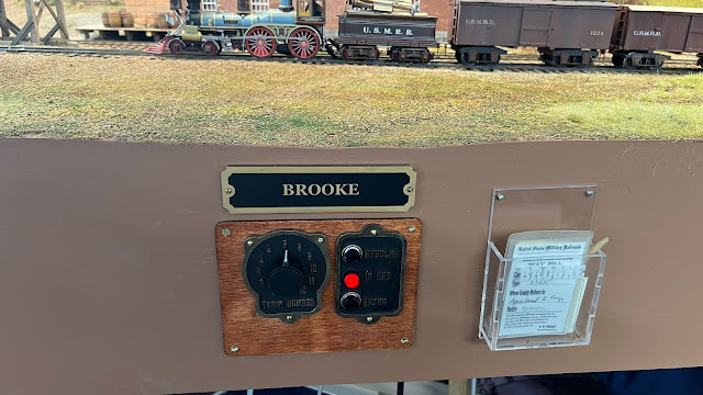
Telegraph installed and working at Brooke 

Amby stopped by this morning to help finish the installation of the telegraph system. He ran the last cable to Falmouth while I finished building the panels for Brooke and Falmouth.   All went fairly smoothly except for me accidentally installing the Falmouth panel at Brooke. That was an easy fix. 

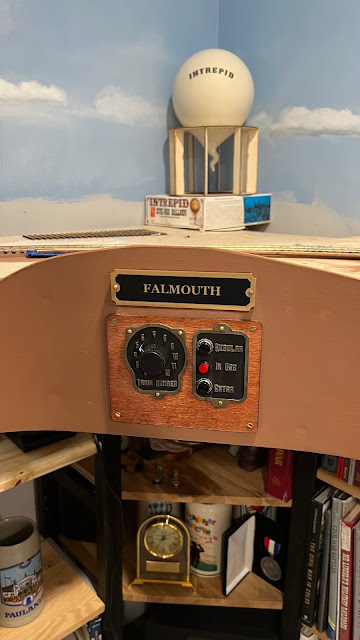
 Location of telegraph station at Falmouth

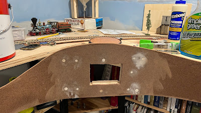
The Falmouth telegraph station is mounted on the curved section of the fascia near the balloon camp and north of the turntable. I needed to reinforce the curved fascia with a scrap of 3/4 inch plywood to flatten it out and stiffen it.
First I wet the fascia to allow it to bend more easily. Then I glued and screwed the plywood to the fascia. After a few hours it was ready for cutting the hole with the jig saw.

In between putty and paint drying I continued to spike track. Amby also took a crack at spiking. I did not sense a lot of enthusiasm from him for the task. I am not sure he will volunteer for more of  that activity. 

Special thanks to Amby, Seth, and Steve for their help in getting this system designed and built, installed and tested. 

With the telegraph done, now we need to get the track finished. Just about 5,000 spikes to go. 


March 9, 2022

Attention to Orders

 Amby stopped by this morning to see if he could figure out why the telegraph system only works when all the stations are plugged in and turned on. He, Steve, and Seth think it is something to do with the ground not being at the proper voltage.  Before he worked on that I presented him with his official appointment as Chief Signal Officer of the USMRR Aquia Line. Amby, in true Hermann Haupt tradition, asked if he could refuse the appointment, but so far he hasn't declined it. He wasn't able to solve the problem, but at least it all works when plugged in. 


Cracked fascia at Brooke.

Meanwhile, I have been working on repairing the fascia by Brooke. It was damaged when the contractors were doing the  flood repairs and they jacked up the layout. 


Room for the telegraph 

I had extended the fascia in the area by the rock cut south of Brooke. That piece of fascia cracked along the seam and became loose when they jacked up the layout. Unfortunately, there was no easy way for me to access it from below to securely repair it. So I took this opportunity to extend the fascia about 3.5 inches. 

This achieves three objectives. First, it will allow me to fix the crack, second, creates a nice secure place to mount the telegraph station at Brooke, and third,  extends the scenery.

I plan to add a large foundry building between the tracks and the aisles. This will create a "urban canyon" for the tracks in Brooke.  I was inspired by the foundry in Fredericksburg that the USMRR used to repair rolling stock in 1862 and the iron works rolling mill on Thom Radice's layout.  The interior of the foundry will have full detail. I haven't decided if I will leave a wall open so one can see the detail, or to make it a fully enclosed building. 

The telegraph is resting where the new foundry building will go.


March 1, 2022

Telegraph System Update


Amby and I worked on the telegraph system today. He got the electronics sorted out using the modifications suggested by Steve Williams. The system is now working as designed, though there are still a few minor but perplexing things Amby noticed in the circuitry.

Meanwhile, I was installing the stations and building the dispatcher panel. The photo above shows the telegraph panel at Stoneman's Station. I also have Potomac Creek almost done. The telegraph stations at Brooke and Falmouth require that I do some repair and prep work on the fascia. The fascia at Brook was damaged when we jacked up the layout for flood repairs. My plan is to replace that section of fascia while also adding about 4 inches of scenery between the fascia and the track. That will allow me to add another big building at Brook between the aisle and the tracks. I am thinking of a foundry with a detailed interior.

I also got a fair amount of work done on the dispatcher's panel. See video below.  The reason for the door is to hide the LEDS that show which station is transmitting. The dispatcher doesn't need to look at them if he or she desires to remain more period-correct as there were no LEDs in the civil war. But the LEDs can aid in debugging the system and help a new dispatcher that is not familiar with the code.


February 24, 2022

Telegraph Problems - now and 159 years ago

Steve Williams, Amby and I had a zoom conference today to discuss the fix to the telegraph stations on the longer cables. They came up with two simple solutions that should work. We will try them next Monday.

We also briefly discussed possible upgrades to the software. We will sort that out further once we have some operating experience.  I was thinking it might be fun to have the random messages lead to things that the dispatcher would have to react to and not just for ambience.  That would require  the dispatcher to translate the random messages and decide what to do. 

I have been listening to the random messages as I work on my computer. They arrive suddenly and often I miss the first sentence as I prepare to copy.  To make that translation easier, the random messages should have a preamble like the others. W-W-W - EoW is perfect.  Also, the message would have to be repeated until acknowledged. 

If we do this, I would need to compose messages that need action. Others can just be for ambience and or information.

The type of action the dispatcher could take include, order out an extra, such as the General’s special, set up a meet, tell a train to pick up a certain car , etc. Since the telegraph system is one way, the DS would write the message on a paper message slip and place it manually on the layout for the conductors to pick up.

We will see how hard it will be to upgrade the software. I am sure Steve could do it, but how do we get the new code into the installed stations? We may have to learn how to program the Arduinos. That looks more complicated that I want to take on, but every journey begins with the first step.

Meanwhile, we are not the only Aquia Line telegraphers to have problems. I found this letter while going through my files. I believe this letter was in a book in the Library of Congress that contains many of Herman Haupt's letters transcribed as well as some seemingly original, or at least hand written messages, from Haupt's records. Those messages were donated to the LoC by one of Haupt's sons well after the war. This is a link to the citation https://lccn.loc.gov/mm73025296 

If you can read this, you can see that W.W.Wright is complaining to Haupt about being unable to get reliable service from the telegraph. I believe this was because regular Army traffic was monopolizing the telegraph. This was after the battle of Chancellorsville and the Army was actively campaigning. 


 Letter from W.W. Wright to General Haupt

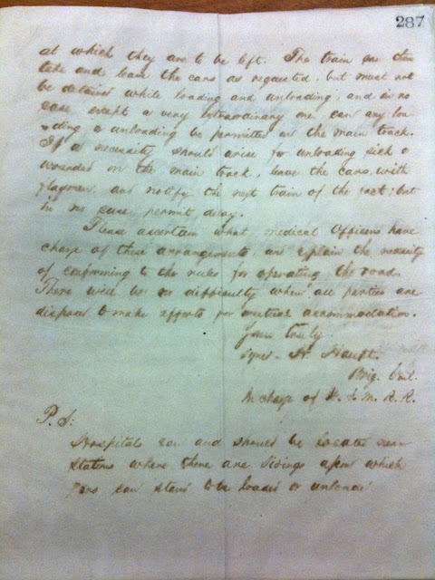
In that same batch of letters was this one from Haupt to Wright discussing how trains own the Aquia Line  were delayed to pick up wounded. The Army medical officers were using an ad hoc system to load wounded that was delaying the USMRR trains. Haupt would not have that!


Page 1

Page 2


February 21, 2022

Telegraph Installation Begins

Amby helped me install the telegraph system today. I made a short video describing its operation.

We have all the cables run and one of the 5 stations,  Aquia Landing. installed. It works as designed, which is very rewarding.

We did test the other 4 stations and we found a glitch. They will light the LEDs in the dispatcher panel, but will not drive the sounder. Amby thinks the problem is in the diode stacks that control the LEDs and the length of the cable affecting the overall voltage drop in the signal. The system worked fine at his house with shorter cables, so he suspects that is the issue. 

I have a lot of work to do this week in building and installing the stations. I also need to finish building the display panel on the dispatcher desk.  Amby will be returning next week to continue the installation. 


February 20, 2022

Telegraph Key and Sounder


To build the telegraph key and sounder for the dispatcher's desk, I first did some searching for ideas on how to arrange the components. There are many pictures of telegraph keys and sounders available on line, but very few of them are from the civil war era.  I could only find one period photo on the Library of Congress website that shows the actual telegraph instrument.

Here is a close up of it. This appears to be a combination style device with relay and key built in. There is a drawing in Frank Pope's book of 1881 of an instrument like this. The large coils are part of a relay to amplify the line signal, "the relay is constructed with great delicacy, a feeble line current is enabled to actuate a register powerfully through the intervention of a local battery." However, I think in this picture, there is no register and they just use the sound of the relay clicking to listen to the code. 


I decided to make my key and sounder as a combination system. I bought a piece of Brazilian cherry. I cut and routed the edges  to look like a typical base for a combination instrument. I stained the wood a dark walnut color. Here is a photo of the mock up of the combination base with a key and sounder on the board as they would appear on the dispatcher's desk.

I ordered some antique brass knurled knobs and screws to use as terminals for  the various wires. They have not arrived yet. Once they arrive, I will finish the central panel. That is where the LED light display will be hidden behind a small door. The dispatcher can open the door to see the lights. Each station will have a light that flashes when that station is sending a message. It is not period correct, but could help a new dispatcher that is not familiar with the code. That was a feature that Seth and Steve added. I did not have it in my original spec. A nice example of defense contractors "gold plating" their systems!

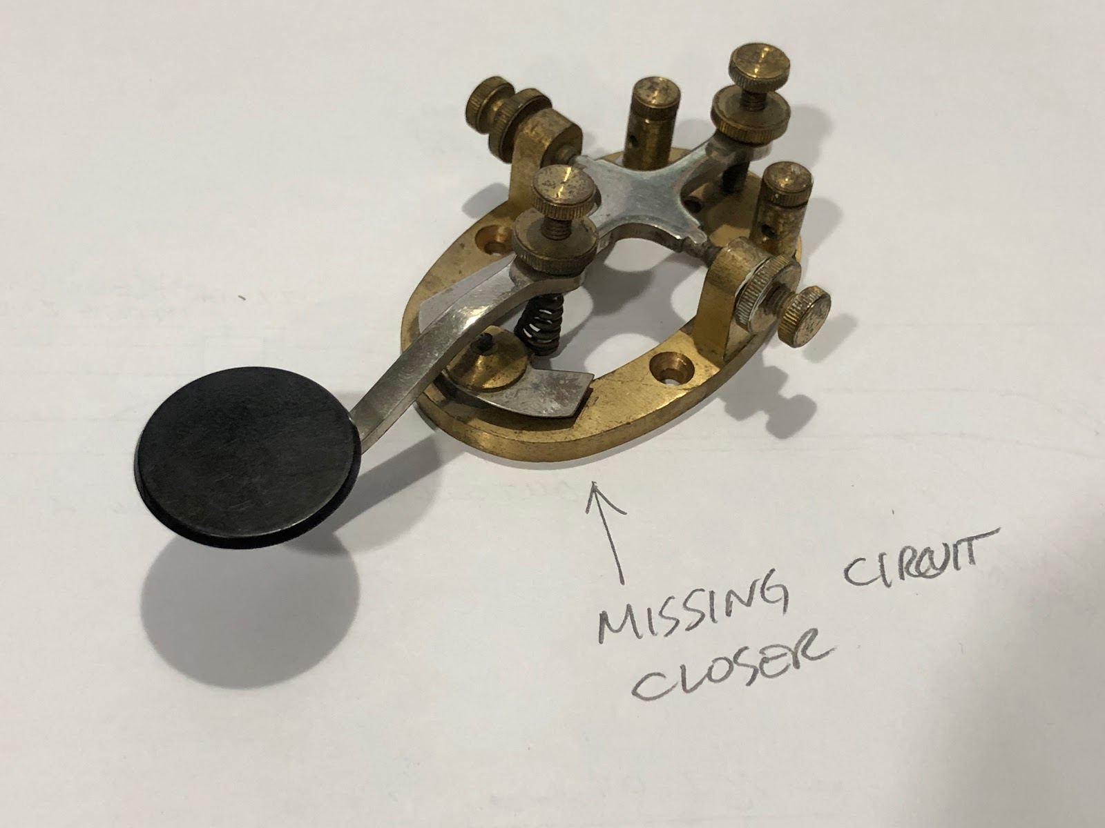
In examining my key, I noticed that it is missing the circuit closer switch. The operator is supposed to use that switch to by-pass the key, so that messages can be received. However, in our system, we plan to use the key only as a momentary on-off switch. We don't need the circuit closer, so I think this will work in this system.

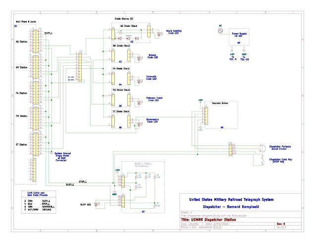
Meanwhile, Amby has been busy documenting the wiring of the overall system. There are a lot of wires and cables, but it is not as complicated as it may look.  We plan to begin installing on Monday.


February 13, 2022

Rock Me Some Wagon Wheels


...with apologies to Bob Dylan, to finish up the cannon I had been working on, I drew some 14-spoke wheels. I had some artwork for wagon wheels from Gerry Dykstra, but that was not in a format I could edit.  So I decided to draw my own. To get the model as precise as I could, I went up to Fort Ward to measure the cannons they have in the restored bastion. One of their  guns is a very authentic replica of a 6 pound James Rifle. 

I was able to get detailed measurements of the wheels. The hubs in particular were quite interesting with a cove on the inside and an ogive on the outside. Also, I measured the amount of dish in the wheel. It was only 2 inches, but that is an important feature of wagon wheels from this era.

I also measured the 24 pound howitzer they have on site. It is slightly bigger that the 6-pounder but only by about 4 percent. 

While I was at Fort Ward I stopped by the Museum and visited the replica of the officer's quarters. I took a panorama of the inside of the officer's quarters. I need to recreate something similar on my layout. I plan to detail the upper story of the Provost Marshall office. So this photo will help guide me. I also had a nice chat with the museum director as she and her colleague were wondering why I was measuring their guns.

Interior of officer's quarters for detailing ideas. Looks cozy.


Telegraph System


Amby continues to make amazing progress on the telegraph system, He now has all five base stations done. 

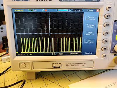
I think he has been having fun with them as he sent me this image of the dot code on his oscilloscope.  I was playing around with speeding up the code. I think it might be a tad easier to listen to at about 25% faster than what we have now.  It remains to be seen if we will be able to change that in the software.


 It is time to begin wiring the dispatcher's control station. That will be built into the cubby hole section of the dispatcher's desk. 


When I built that cubby hole I was inspired by the field desks that civil war officer's used. It happens that the museum at Fort Ward has one of those on display too.


Each individual station will be adorned with simulated brass plates that I printed on my 3D printer. I now need to finish painting them. 


February 5, 2022

Telegraph Progress Continues

Amby stopped by this afternoon so we can review progress of the telegraph stations. I needed to make more base plates for him so he can continue to build the stations. He has completed one and plans to rewire the one I built as that one has some loose wires. That is probably due to my lousy soldering and its two trips across the country. 

Here you can see the two stations completed so far "talking" to each other.  The red flashing light tells the train operators that the telegraph is busy and to not try to send an OS report until that stops.  All the stations will flash a red light when a message is being sent from any one station. Amby suggested a revision to the busy  circuit so that the busy light stays on continuously while messages are being transmitted. That is probably a better way to do it as then the operators won't get fooled by halts in the flashing due to delays in between messages. 


Amby is approaching the task very methodically. He is creating circuit diagrams of the whole system so it will be easy to understand and debug. He made a spreadsheet listing all the wires and their color codes.  He also wants to dig into the Arduino code to better understand that. I am really benefiting from his experience and an EE.

Next we surveyed the locations of the telegraph stations on the model railroad. We need to find places where they will be out of the way and have sufficient room for the electronics behind the fascia. There are good places for all of them except at Aquia Landing. At the location I may have to make a separate station base plate as the fascia is only 3 inches tall.

Amby also suggested a cheat sheet with all the possible OS messages listed so that guest operators can dispatch more easily. However, he did not know about the random messages that I added to the spec and Steve Williams included in the software. There are about 10 messages that play at random. Those messages are based on actual messages I found at the National Archive. Amby told me that he had left the telegraph system hooked up at his house while he was working on something else. At one point it started to send a message. He was quite surprised by that as he did not know about the random messages. 

While Amby was wiring this week, I took a crack at making simulated brass plates using my 3D printer. I was able to use the existing 2D artwork that I generated for the laser cutter to create the STL files needed for printing. I imported 2D dxf files into Fusion 360 and made them into 3D objects. Once I converted them to STL files I printed them in resin.  I did get an estimate from Shapeways on printing these in actual brass. The cost was over $115 per plate. I would need 5 of these, and 5 smaller plates for the lights. That was too costly as I can make them in house with resin for far less.

Next I needed to paint them. It took me a few tries, but the best results came by spraying the model with flat black Vallejo acrylic. Then I carefully brush painted the raised letters and brass surround with acrylic gold craft paint. I used a dabbing motion with a nearly dry brush so the gold paint would not soak into the gaps between the numbers.  Then I gave the model a coat of clear gloss acrylic. They might look better with a matte finish. 

Visit to John Sethian's O Scale PRR layout

Action on John Sethian's PRR O Scale layout. The clock tower conceals a support post.


On Saturday Morning I had a chance to visit John Sethian's O scale 2-rail PRR layout. It is a gorgeous layout depicting Pennsy RR action in the electrified districts somewhere near Trenton, NJ. He is building catenary for his electric motors to run under. The catenary is not live on his railroad. John has very cleverly modified many 3-rail models to 2-rail to get the equipment he needs for his railroad. 

I like how he uses large urban buildings as view blocks. He also uses forced perspective on the background scenery and structures made from photo prints. His layout is full of finely detailed scenes and clever  devices. For example, he has a section of scenery that lifts out of the way using a linear actuator.

Here are examples of two finely detailed scenes. The office is based on a Edward Hopper painting. The used car lot contains models of all the cars John has owned now or in the past. He had a Porsche at one time, but he really is a Jaguar aficionado. In fact his garage has three of them, including an XKE that he purchased after it was on fire and totally rebuilt.


John posing by his Jags


Work session at Doug Gurin's layout


On Thursday, I was at Doug Gurin's house to continue to help him build benchwork. We got a tricky piece of  sky board installed on a very rough cinder block wall. Then we cut the plywood bench tops for the long wall. A few more sessions and we should have Doug's benchwork ready for him to lay track. 

February 2, 2022

Amby to the Rescue


 If you read my blog, you know I hate wiring and electronics. In the panoply of model railroad tasks required to build a layout, I rank wiring and electronics rank at the bottom.  So I was delighted when Ambrose (aka Amby) Nangeroni offered to help finish build my telegraph system. Amby is an electrical engineer from Northeastern University. He has a lot of experience with model railroad electronics.  He said he was willing to work on building the components at his home to minimize possible exposure to COVID as he needs to be extra careful. 

I sent him copies of the documentation I had, plus a copy of the video of the prototype system in operation. He studied them before visiting and had some very interesting observations.  He also asked me some questions that required me to review the documentation as it was long enough ago for me to forget the details.

After I made that video mentioned above,  I had to send all the circuits back to Seth and Bill of https://www.modelrailroadcontrolsystems.com/telegraph-sounder-driver/ for some software revisions. That was about 2 years ago. They returned the updated parts to me and I promptly put them away. I had not worked on them since then.  

Today, Amby stopped by my house to see  the system as it stands and to better understand the design and application. 

It was a thrill to get the parts out of storage and  working again. Amby was very helpful in debugging some issues we had. A few wires had come loose while the parts travelled back and forth across the country. In addition, the antique sounder that I sent to Seth, got broken in the shipping process. The super fine 100 year-old paper-wrapped insulated coil wires broke. Seth sent me a replacement sounder as repairs to the old coil looked difficult. But the replacement sounder was not working. The reason was perplexing at first, but simple once Amby figured it out. All the contacts inside were corroded and needed some maintenance.


Once we sorted out the sounder, we were able to get the prototype station that I had assembled three years ago to work. We verified that the new software works too.  Amby now has all the circuits at his house and will work on assembling them as his schedule permits.  Here is a short video he shot at his house showing the original system in proper operating condition.


I plan to make the base plates. At first I used wood and laser cut plastic to make the panels. But I now will try to make 3D printed panels that will be painted to look like brass. I'm aiming for a brass builder's plate look, hopefully one that conjures up a 19th century vibe. 

Amby also has some ideas on how to run the cables from the stations back to the dispatcher. He recommended prefabricated  CAT6 cable with plugs and sockets, vice the terminal strips I was thinking about using. 

In retrospect, I should have designed each station to connect to a data bus as opposed to individual CAT6 wires from each station to the dispatcher.  That way we could run just one pair or wires to east station. Each panel would need a data bus interface, and there would need to be some kind of bus controller, but I suspect such circuits are available off the shelf. It might be possible to add that feature on to the existing system.  If anyone has any suggestions on how to do that, please let me know.

Last week Paul Dolkos and Ted York visited the Aquia line. Ted was in town to receive an award for a photograph he took, and Paul has showing him around.

 The stunning image depicts wild mustangs in an action shot. They look to me like they are fighting. You can see Ted's photo here https://www.worldphotographiccup.org/wpc_gallery/finalists-2022/

In case you don't know, Ted also has a fantastic HO model railroad depicting the Santa Fe over Cajon Pass. I have operated on Ted's layout a couple times and it is a hoot.

June 15, 2020

New Flag for the Dispatcher

I received a new 34-star United States flag for my dispatcher's office. The new flag is 100% cotton with embroidered stars. It replaces a cheap nylon flag that I had previously.

The 34-star flag was in use in March, 1863, the time that I simulate on my model railroad. West Virginia would join the Union a few months later making 35 states and stars. If you are wondering about the star pattern, many variations were in use at that time.

The lantern is replica. The telegraph instruments are not yet connected, but we are working on that. 

I suppose I need a period coat rack for the brigadier general frock coat.

My bother painted the portrait of Lincoln. The Engineer Castle was also a gift from my brother that he acquired in Korea for me in the 1980s. He and I were officers in the US Army Engineer Corps. The Engineer castle insignia was in use by Union engineers in the civil war.   
"The Army unofficially adopted the castle to appear on the Corps of Engineers’ epaulets and belt plate in 1840. Soon afterwards the cadets at West Point, all of whom were part of the Corps of Engineers until the Military Academy left the charge of the Chief of Engineers and came under the charge of the Army at large in 1866, also wore the castle on their cap beginning in 1841. Subsequently, the castle appeared on the shoulder knot, on the saddlecloth, as a collar device, and on the buttons. Finally, in 1902, the castle was formally adopted by the Army as the insignia of the Corps of Engineers. Although its design has changed many times since its inception, the castle has remained the distinctive symbol of the Corps of Engineers."


June 7, 2020

Crazygrams

 
We have all seem the internet meme with a quote attributed to Abraham Lincoln about not believing what you see on the internet. However, there is this little story about Lincoln from the book, "Lincoln in the Telegraph Office; recollections of the United States Military Telegraph Corps during the Civil War," by Homer Bates, that reminds me of internet craziness. It was a portent of the future.  But first, I want to discuss this remarkable book and some other books a bit more. 

The Bates book is fascinating. You get a detailed look at what happened in Washington, DC from the perspective of the clerks that saw every telegram that came in. It makes the shenanigans that go on now look like kids play. I tell people, "the  more I study the Civil War (and Revolution) the more I realize very little has changed in Washington politics."

For example, at times the clerks edited messages that came in from senior officers, or even withheld some to avoid trouble. One time they deleted a paragraph that contained an insubordinate remark that McCellan sent to Lincoln after the Seven-days campaign. The clerk freely admitted he could be shot for doing it, but he thought it was the right thing to do.  

There is another incident described where a Norfolk doctor murdered a Union officer, who was in charge of a colored regiment,  on the streets of Norfolk because the idea of African American soldiers incensed him. The doctor was quickly captured, tried and sentenced to death. First the doctor tried to escape prison by exchanging places with his daughter. That didn't work. Then the defendant appealed to Lincoln, but he did not grant clemency. The allies of the doctor tried to bribe a telegraph agent to write a false message of clemency, but the bribe was not accepted. The doctor was hanged.

The book covers a series of incidents where Democratic supporters were trying to organize military officers to become political opponents to oust Lincoln. Then they would end the war and let the south secede.  The plot failed when General Rosecrans and others did not support them and their plans were upended.  However, later they did get former General McCellan to run against Lincoln, but Lincoln defeated him in the election.

Of interest to my railroad, there is discussion a rebel spy who was tapping the telegraph line on the Aquia Railroad. The union telegraph clerks actually heard him but could not physically find him. The telegraph operators used ciphers so that the spy couldn't understand what they were saying. He eventually did give up and they later found where he had tapped the line.  

The book goes into great detail about ciphers that were used to encode messages. The telegraph lines around the nation were not secure and could be tapped anywhere. At one point, Grant's men intercepted several messages near Vicksburg. The messages where in a crude code used by the rebels. Grant's men sent the messages to Washington. There, the telegraph staff decoded them and sent the clear text back to Grant.    

In addition to eavesdropping, the opposing sides also used to send spoof messages. These were often not effective because the operators could recognize each other by their telegraph key technique (what we would call electronic signature now) and could tell when messages were from others. 

Union telegraph operations were much more sophisticated that the rebels. By 1864 Grant's signal corps was laying telegraph line at a rate of two miles per hour. Not only was Grant in constant communication with Washington, DC and hence the rest of the United States, but he also had lines from Army to Corps HQ for more tactical communication. The rebels had no such capability.

You can download the book for free from the internet archive.  

I also recommend, "The Northern Railroads in the Civil War, 1861-1865, " which I reread this past week. I am in the middle of "Gettysburg: A Testing of Courage by Noah Andre Trudeau." It's a highly readable account of the campaign and battle which combines great prose with a nice assortment of original quotes.  

Another book that I just finished and recommend for anyone interested in the Aquia Line is "Seizing Destiny: The Army of the Potomac's "Valley Forge" and the Civil War Winter that Saved the Union," by Albert Conner Jr.,  Chris Mackowski. The book goes into great detail on the reforms that General Hooker introduced to re-build the Army of the Potomac into a war-winning force. Some of Hooker's reforms still persist, such as the wearing of unit patches on uniforms, and a centralized military intelligence staff. 

Now, back to original story I cited at the start. Here is some background. Maxwell, an ordinary citizen from Philadelphia, would constantly telegraph President Lincoln with criticism and complaints about various political issues. Lincoln would often respond to them out of courtesy. This message came in after the Battle of Chickamauga, where General Thomas earned the nickname, "Rock of Chickamauga." The following is an extract from the book. 

"...The next Maxwell telegram of record was as,
New York City, 1:30 p.m., September 23, 1863.His Excellency A. Lincoln, President: Will Buell'stestamentary executor George Thomas ever let Rosecranssucceed? Is Bragg dumb enough to punish Thomas severelyand disgracingly ? Robert A. Maxwell. 

The President held this impertinent telegram until his evening visit to the War Department. Meantime, no doubt thinking that some defense of General Thomas by the Administration might serve to allay the already evidently wide-spread distrust and anxiety, he wrote the following despatch at the White House and brought it to the telegraph office and handed it to Tinker for transmission: 

"Cypher"Executive Mansion, Washington, Sep., 23, 1863.Robert A. Maxwell, New York: I hasten to say that inthe state of information we have here, nothing could bemore ungracious than to indulge any suspicion towards Gen.Thomas. It is doubtful whether his heroism and skill exhibitedlast Sunday afternoon has ever been surpassed inthe world. A. Lincoln. 

But the message had been in Tinker's hands only a few minutes, when Lincoln came over to the cipher-desk and said, "I guess I will not send this; I can't afford to answer every crazy question asked me." 

Thereafter, adopting Lincoln's description, we always referred to these officious despatches as "crazygrams." 

Tinker, of course, did not send the message which Lincoln had written, and deeming it of curious interest as a memento, preserved it carefully with a copy of the message from Maxwell. Several years afterward, he met General Thomas in Washington, and thinking he would be especially gratified to see and possess the documents, he had the pleasure of delivering them into Thomas's hands at Willard's Hotel, Washington, with a letter, of which the following is a copy.  

May 27, 1867.Major-General George H. Thomas,General : I have had in my possession since the day it was written, a telegram penned by our late beloved President. Its history is this. Robert Maxwell, a quixotic individual, residing in Philadelphia, has during the war, and since, humored a propensity for addressing dictatorial and sensational despatches to the President, his cabinet and prominent officials of the Government. By those who were familiar with his character, no consideration was accorded them. On receipt of one of these, a copy of which I enclose, the President wrote a reply, which he handed to me for transmission, but afterwards concluded not to send.I have preserved this precious autographic document, hoping some time to be honored with an opportunity to present it to you in person, to whom it justly belongs—a priceless tribute to a noble hero, whose dauntless courage on that fateful day saved the Army of the Cumberland.Very Respectfully Yours,Charles A. Tinker, Cipher Operator,War Dept. Telegraph Office.

January 19, 2019

Dispatcher's Telegraph Station


I finished building the desk for the dispatcher's telegraph station.  I still need a few items to make the look more authentic such as a vintage clock, appropriate  artwork, a lantern, ink well, wooden chair, and a telegrapher’s key. And yes, the flag is correct for March 1863. It has 34 stars as West Virginia is not yet a state.  The USMRR did have lanterns with their initials on the glass globe. It would be awesome to find one, but in the meantime, a regular lantern will suffice.'


Note that the artwork of the Baldwin  Tiger 4-4-0 is a silver on glass "print" from the Franklin Mint that my parents bought about 50 years ago to decorate the bedroom for my brothers and I.  Was this a foreshadowing of what was to come?

This was the "easy" part. Next comes wiring of the control panels at each station. The solid panel in the center will display the station lights and a "clear" button.


Using a track saw and parallel guides to rip pieces as I
don't have table saw. The parallel guides
are a bit tricky to calibrate, but they can result in
good cuts.
Here are some photos showing the construction of the desk and cubby holes. Alicia says I should build chair for it too. I think I'll just buy one.

I used tools from the Festool system to fabricate the parts. The Festool system is ideal for a small shop where you don't have room for lots of bulky, specialized tools, like a table saw.  However, this project  convinced me that the next job will be to build a workbench that allows me to access the Festool boxes without having to unstack them when I need a different tool.


Cutting the top to size using Parf dogs and a Festool MFT to
keep the track saw square.

I used a Festool domino to machine attach the
legs to the frame. However, the tool visible in the photo is a
Festool Rotex sander, probably the tool I used the most in this project.
The dust collection of this tool is outstanding.

Drawer is full extension.


I used lots of clamps to glue the face frame to the pigeon hole box

January 14, 2019

60 Amps of Power

I finished the secret project I mentioned in my last post. It was an animated version of a bedtime story that I used to tell my kids. You can see it here if you wish. It was a lot of fun to make, but also a lot of work. I had help from my wife and niece as they provided voices.


The electrician was able to use existing speaker holes
in the ceiling  to avoid cutting holes over PoLA.
In the meantime, I had an electrician work on improving the electric service to my garage workshop. He took care of the electric stuff by running a 220V, 60 Amp line, while I did the sheet rock repairs where he had to cut holes in the ceiling and walls.

Luckily, the wiring work did not affect the areas by the layout, but my office had to be cleared out to allow the work to proceed.

In moving the book shelves around, I realized that I will have to rebuild them. The thought occurred to me that if I made new bookshelves,  I could build a nice small shelf layout into them. The mind boggles at the possibilities.  But, that is a project for later. For the present, we have enough power in the garage to run all my tools, as well as the capability to add a charger for an electric car, if and when we get one.

Brian eying over my stack of N Scale DRGW stuff
During the wiring upgrade process, we had a surprise visit from Brian and Jake Brendel. Brian was in town for a fire department memorial service. They had a chance to familiarize themselves with operations on the Aquia Line. Hopefully, they will be back for a full session.  I took pleasure in seeing that the Aquia Line ran well for them in what was essentially a no-notice inspection!

With the garage powered up, I continued to work on the desk for the telegraph dispatcher. The top, legs and frame are ready to go. I just need to decide if and how I can add a drawer to the desk.  This was the first time I used the Festool Domino system to make floating tenons. It really is a neat system. It's probably too expensive to recommend for model railroad benchwork, but it sure makes nice joints.  I may try some benchwork with this system in the future, maybe for a module frame.

Jake running a train into Falmouth
While I am working on the desk, Seth and Steve revised the software for the telegraph system. The revised chips and boards should arrive any time now, so we can renew work on the telegraph system electronics.


Gluing up the legs for the dispatcher desk
Cutting the desk top to size with my track saw