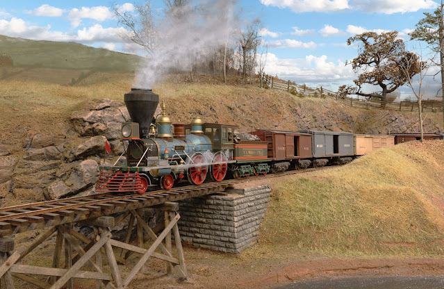
A journal following the history, design, construction and operation of Bernard Kempinski's O Scale model railroad depicting the U. S. Military Railroad (USMRR) Aquia-Falmouth line in 1863, and other model railroad projects.
©Bernard Kempinski All text and images, except as noted, on this blog are copyrighted by the author and may not be used without permission.
-----------------------------------------------------------------------------------------------------------------------------------------------------------------
Showing posts with label Locomotives. Show all posts

May 7, 2023

Pig Pen Palace

Eclipse stands ready while a gun boat comes to shore to get resupplies.

Improvements to the pig pen
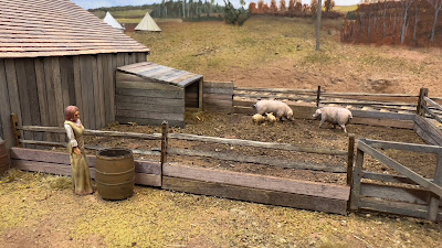
The farms boys suggested that I make the dirt in the pig pen darker to reflect the typical mix of mud and manure found there. They also suggested some type of shelter for the pigs to get away from the weather.  

So I painted the soil with a dark umber color acrylic wash that I stippled on to the existing scenery. I made a small lean-to shed and placed it in the corner.  I put some straw on the ground so the pigs have a nice resting place. I also added boards to the lower edge of the pig pen to help keep the little porkies in the pen. 

Meanwhile, I noticed that the Eclipse headlight was not working. A brief investigation revealed that one of the CVs controlling the head light was somehow set to 63 vice 2 that it was. I don't know how it changed.

But the Eclipse was not done with me yet. As I was test running it, it started stuttering and growling. The source of the problem was the lead weights in the tender. The CAA joint where I glued them to the tender had failed. Some off the weights came loose and were interfering with the drive shaft to the rear truck. So I had to disassemble the tender once again. In the process, the red and black power wires broke off at the plug connection to the engine. So I had to resolder those. Good news,  all is back together and seems to be running well.  

Finally, I did some tuning of the double slip stub turnout in Falmouth. I noticed that the switch stand was not tightly mounted to the extended tie. So I used some 5-minute epoxy (which is really 30 minute epoxy) to reinforce the base. Once that was cured, the switch stand was solidly mounted, 

May 2, 2023

TOTAL ECLIPSE OF THE GENERAL


The final step to converting the General for use on the  USMRR Aquia Line was to rename it. I selected the name Eclipse with some advice from John Ott. See this discussion here. The other option was Warrior, but Eclipse won out since it was actually used on  the Aquia Line.  

 I made the new name tags using micro-thin laser engraving plastic. It was black on brass with a self adhesive base. The labels can be removed if someone wishes to go back to the name W&ARR General. 


April 30, 2023

The General is ready


I finished all but the final decal on the General. 

First, the continuing saga of the headlight. The 1.5V bulb in the headlight burned out after a few hours of test running. I decided  to replace it with a LED. This was a bit tricky as I had to machine the diameter of the LED to fit the headlight housing. Once I had it installed, I discovered that it would turn on nicely, but when I turned it off, it remained very dimly lit. I decided to change CV57 and CV58 to 2 based on a recommendation from George and that solved the problem. The headlight is now controlled independent of direction, that is, you can turn it on or off regardless of which direction the train is running.  Railroads in this era did not burn their headlights in daytime, so it will be off for most op sessions.  The LED gives a nice warm white color. 

Next I painted the resin woodpile with acrylics and washes. 

I dug through my stash and found two figures that were suitable as engineer and fireman. I repainted them in shades of brown, dark blue,  and gray. I added a piece of firewood in the fireman's arms.  Both figures are now glued in the cab.

I made a new extended link for the cowcatcher. The new one will allow crews to use it during op sessions. The old one disappeared into the carpet monster even though my floor doesn't have carpet. 

Finally, I lightly weathered the model with some chalk, enamel grease paint from MIG, and acrylics. I added a bit more rust than normal to the ankle rail. I carefully sprayed the painted (vice russia iron) surfaces with dull coat being carefully to not get paint on the wheels.

The last step will be replace the decal on the tender. I ordered a new decal paper than might make that job a lot easier.  We shall see. 

Crew figures and tender are visible from this angle.


Speaking of the ankle rail. As I was test running I discovered that this loco, with its ankle rail, is wider than my others. There were two locations on the layout where the ankle rail hit the scenery. One was in Stares Tunnel and the other was in the rock cut just south of the Mueller's Creek trestle.  I fixed both of those locations by trimming away some scenery.

I also discovered a few places where the gauge was off. The most serious was a kink that developed in a joint in the flex track in Stares tunnel. That caused the rails to be slightly out of gauge, but it only affected a couple cars.  I tried to remove the kink and get the track back in gauge using large track nails driven in the plywood roadbed. To be extra sure, I added a guard rail on the inner rail to keep the wheels on the rail.  So far so good. It should be ready for the op session next weekend. 


April 25, 2023

General Success

 I finished working on the decoder for the General. I was assisted by advice from George Bogatiuk of Soundtrax. He suspected that the output for the headlight was damaged during my installation. He said repairs would be covered by warranty. However, if I only needed a headlight, he suggested wiring the headlight to the yellow wire that usually controls the  back-up light.  That sounded better than taking out the decoder and sending it back. 


So that is what I did. 

I also had to modify some CVs. Normally this would be a trip to hexadecimal hell. But this was very easy to do using the Blunami Ap - heck - even I did it. First, I did a total decoder rest by setting CV 8 to 8. You have to power down the decoder for the reset to take effect. Then I input 63 in CV 57 and 0 in CV58.  Now the head light works. I used the ash pan effect on it per George's recommendation and it looks very much like an oil lantern.

Then I did some test runs. I suspected that this locomotive would not pull as much as the Fury (nee Texas) and the Masons. The motor in the tender is a bit smaller than those and the tender is lighter. To improve the pulling power I added weight to the bottom of the tender and inside.  However, there isn't that much space in either location.  Based on my tests, the loco needs about 4 ounces to pull 9 cars up the ruling grade. I could only fit about 2 ounces. 

I also had a scare as I tried to shoe-horn in as much weight as possible. I accidentally popped off the prop shaft to the rear gear box. Luckily I found it and was able to replace it. 

I used my dremel tool to grind away the thick resin of the factory wood pile to make room for the speaker. It now fits snuggly on the loco but can easily removed for maintenance. Being thinner, it provided less muffling to the sound from the speaker below it. I sprayed it dark brown. I will finish painting it later. 

Here is a quick video showing the engine in operation. It can easily pull six cars. I will do more testing to determine its maximum capacity.   I still need to weather, paint the wood pile, fix the front link and add crew figures.


April 21, 2023

Success, ...almost


Test running the General 

I installed a Soundtrax Blunami decoder in the locomotive General today.  That involved installing the decoder, current keeper, speaker and adding a working headlight.  It went fairly well. Overall, I am very impressed, but there is one lingering issue.

Installation

All the electronics fit in the tender
The first thing I noticed was that the wire to the  electrical pick-up on the pilot truck was broken. This is a common problem with these locos. The Osceola had the same problem and I fixed that yesterday.
 
I had to remove the pick-up to clean off the solder joint and solder the wire. 

Next was the decoder. Installing that in the General was much simpler than my previous decoder installs because I did not add all wheel pick-up to the tender and I did not use the Stanton battery and battery power supply. Thus, there was enough room in the tender to install the decoder on one side of the motor and the current keeper on the other.

I added a sugar cube speaker on top of the gearbox for the lead truck. It sounds great.

This loco has electrical pick-ups for one rail on one side of the tender and for the other rail in the engine. I usually add all wheel pick-ups on both sides of the tender, but this locomotive seems to be running well without them. We shall see how it does when the wheels get some dirt.

I wanted to add a working head light. As installed at the locomotive factory, the headlight light comes on whenever there is voltage on the rails. So it was always on when placed on DCC. 

I had to take off the fire box to get  at the head light wires inside the boiler. The wires from the light were attached via a mini plug to the main power wires of the locomotive. It was easy to unplug it. 

However,  I misunderstood the Blunami instructions and connected the headlight to the decoder output without a ballast resistor. The headlight in the loco was working with 15V from the DCC track power.  So I didn't think I would need a ballast resistor. Oops, that was not correct. The bulb burned out after a brief moment of working. 

The dang headlight won't turn off
So I replaced the blown bulb with a micro bulb I had on hand with a 460 ohm resistor. Now the head light is on but it won't turn off. I suspect I somehow damaged the lighting circuit or perhaps I have an incorrect setting in the control application.  Which leads me to the next part of installation, the Blunami Application.


The Blunami Application

Downloading the Blunami Application to my iphone was easy. I fired up the app and it quickly connected to the decoder. The controls are easy use.  I really like it. The throttle response is excellent. I tested it from various rooms in my house. It works all over the basement and I can even control trains from the kitchen. 

The buttons on the ap have an audio or haptic response, so you  feel like you are pushing a mechanical switch instead of a screen on a phone. It is much better than I expected. One thing I noticed is a slight delay of about 5-10 seconds from when you open the ap to when you can control the loco. This caused a few moments of panic until I got used to it.

Programming is easy. I tried various settings for sound and speed control. It will take some more playing around to get things dialed in. I tried the digital engine calibration. It worked automatically. I really can't tell if it made a difference but it was easy to use. I think it might be chuffing a bit to much, so that is a parameter I need to play with some more. I have to say it easier to program the decoder functions with this device than any other way I have tried. 

I only have one iPhone, so I don't know how I will deal with multiple engines and users. My operators can easily download the ap if they have an iPhone. But not everyone does. What if I want to run two or more engines? 

It is perhaps fortunate that I am using this ap as two of my EasyDCC throttles have stopped working. So, I am down to one functional EasyDCC throttle and 3 throttles that work with the Stanton systems. I haven't decided if I will convert my other locos to Blunami.  

Remaining Issues

I need to find out why the headlight won't turn off or react to any controls. The Aquia Line doesn't use headlights in daytime, so I can disconnect it, but I want to get it working properly. 

Since this loco is the famous W&A RR General, I decided to keep the name the same. However, I made a sticker with the USMRR logo for the sides of the tender using my laser cutter and brass micro thin plastic.  The sticker is removable in case I need to sell the loco. It can go back to being the W&A RR General. 

I need to work on the woodpile and add some weathering. The front link needs to be modified for use with my couplers. I also need to tweak it a bit as I run it and find problems. But it a nice addition to the fleet. 


March 27, 2023

Back from RPM East with a Blunami

 I returned from the RPM East 2023. I had a good time. It was great to see model railroad friends and meet new ones. 

The meet was held in a local community college without an official hotel. I stayed at a hotel about 6 miles from the conference. I found that to be less than ideal as it was not easy to pop into the room to get stuff, take a nap,  or get a snack compared to when the meet is held in a hotel.  

The facility itself was quite modern, clean and bright. The clinic rooms, display area, and dealer space were scattered about the facility. So people had to wander about to attend the various events. There was an interesting central area with a library/lounge/cafe where people tended to congregate. But it did seem to lack a critical mass for easy socializing and networking. There were 200 people signed up, but I never got to see most of them. 

The room where I presented my clinic had several computer monitors scattered about the room with a series of tables. People could watch the presentation on the monitor nearest them. But, if I was pointing out something on the screen, they had to look at my screen. My laser pointer did not work on that screen, so I had to use my fingers to point out specific items. It worked, but definitely was not ideal. The set up also had excellent sound, so the videos I played were easily heard, if not too loud. 

I presented my clinic and attended two others. I tried to go to some other clinics but they were standing room only, so I hung out in the display room instead. The clinic rooms were probably too small for the great turnout that they had. 

The highlight for me was a chance to talk with George Bogatiuk of Soundtrax to learn about the Blunami system. I brought some of my battery locomotives with me to display at the meet with the intent to get some of his advice on packaging and how the Blunami might work. Alas, he was too busy to leave his table so we never got to examine my locomotives. Nevertheless, I was impressed with the demonstration set up he had. I had a chance to try the Blunami on an iPad. The ap worked much better than I expected. I decided to get one with a keep alive to evaluate on my O Scale General.

I know DCC brand is like a religion to some folks. But I keep an open mind and will try out anything that seems like an improvement. In my specific case, I am looking at the ease of programming offered by the Blunami and hoping to get better throttle response. I installed the Stanton radio decoders I have  in the metal boilers as the batteries and battery power supply take up all the available space on the tender. So the radio response can be spotty due to the receiver being in essentially a Faraday Cage. I am hoping the the Blunami solves that problem by allowing me to install the decoder on the tender deck with the keep alive in the boiler.


The display room had some nice models on exhibit. George Bogatiuk had his HO scale 4-4-0 locomotive there. He did a very nice job on it detailing and installing electronics. 


I was also impressed with Ted Culotta's exhibit of highly detailed freight car models. 


I departed on Saturday afternoon as I wanted to get to Mainline Hobby Supply in Blue Ridge Summit to talk with Brian Wolfe about some issues for MARPM. While I was there, I purchased a Blunami Sound decoder and keep alive. I hope to install them before the next op session. It is always great to visit that hobby shop. One of the best model train hobby shops in the U.S.

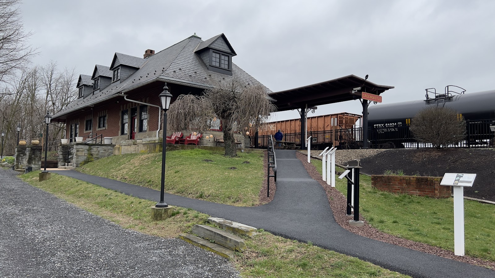
I stopped at the Greencastle Highland Train Station on my way to the Mainline Hobby Supply. I did not know this was a Virtual Railfan camera site. In addition, they have an Automatic Train Control System display in the window of the station to show a real time view of rail traffic on the former PRR, now NS, line. Sure enough, a southbound train was heading our way. So, I stuck around to photograph it.


On Sunday John Burchnal stopped by the Aquia Line to visit. He is in town for a family visit. It's a funny coincidence, as next weekend I will be a guest at his house in Cincinnati. I will be presenting a talk about military railroads to his local NMRA division.

I fired up the layout so we could run some trains and discovered that both of the locomotives I took to the RPM East meet suffered some kind of damage. The damage on the Fury was especially alarming as the valve gear popped out of the cylinder. Fortunately, it was an easy fix. This is why I don't like taking these models to shows. They are somewhat fragile. They don't like being lifted off the track and being exposed to vibrations on a long car ride. 


Whiton will need to have some insulators installed on the tender side frames as the wheels are shorting. It seems that the paint has worn off and the bare metal the side frame is touching the un-insulated side of the wheel sets. 

October 7, 2021

A rose by any other name...

 I asked my friend John Ott for his advice on renaming the locomotive General to use on the USMRR Aquia Line. John is the foremost expert I know on early locomotive history. He provided me with a interesting analysis. Here it is.


Well—if it were me, I'd rename your engine Eclipse in a heartbeat. Reasoning follows:

There weren't that many Rogers engines on the Dept. of Virginia lines. None were 2-steam-dome Rogers resembling General except for maybe Warrior, which never made it to Aquia and got rebuilt into the Lt. Gen. Grant in 1864. Osceola was a Rogers, but you already have an Osceola. There were a couple more single-steam-dome Rogers engines bought after the Aquia line was history.


That leaves you with Lion or Eclipse. Lion was an 1862 New Jersey L&M engine with a single steam dome and oval windows in the cab—in fact, it's my theory that the cab of the Lion was used on the rebuilt Lt. Gen. Grant.


That leaves Eclipse. Eclipse was a single-steam-dome engine built in 1862 by Jersey City Locomotive Works. McCallum's end-of-war report is wrong—he has it listed as another New Jersey L&M engine. It was rebuilt and renamed Scout after Aquia, and was later used in North Carolina


So Eclipse is the lesser-known engine that already has one mistake in its record. The name Eclipse also fits the General's nameplate better than Lion. (This is important!) You can just say that Eclipse and Scout were actually two different engines. In this scenario, Eclipse was cannibalized to rebuild Scout, which is why it no longer appeared on McCallum's for-sale list.

Sometimes I think half the fun of building a model railroad is all the rationalization we come up with to hide our compromises.


I like the sound of Eclipse, but Warrior is also a good possibility as its is the right builder but never ran on the Aquia Line.   

Note that the US Government sold the engines for more than they paid. 

October 1, 2021

The General is Back!


Many years ago I acquired a copy of the SMR Trains General from Charlie Taylor. I missed out on the original production run but Charlie was willing to sell me one of his excess. I had the locomotive for several years as it was a beautiful model. But once I had 5 other SMR locomotives, I began to believe that I really didn't need that many. About that time, I heard through Charlie Getz that Bob Brown, of the Narrow Gauge and Short Line Gazette, was looking for a SMR General. I agreed to sell my copy to Bob.

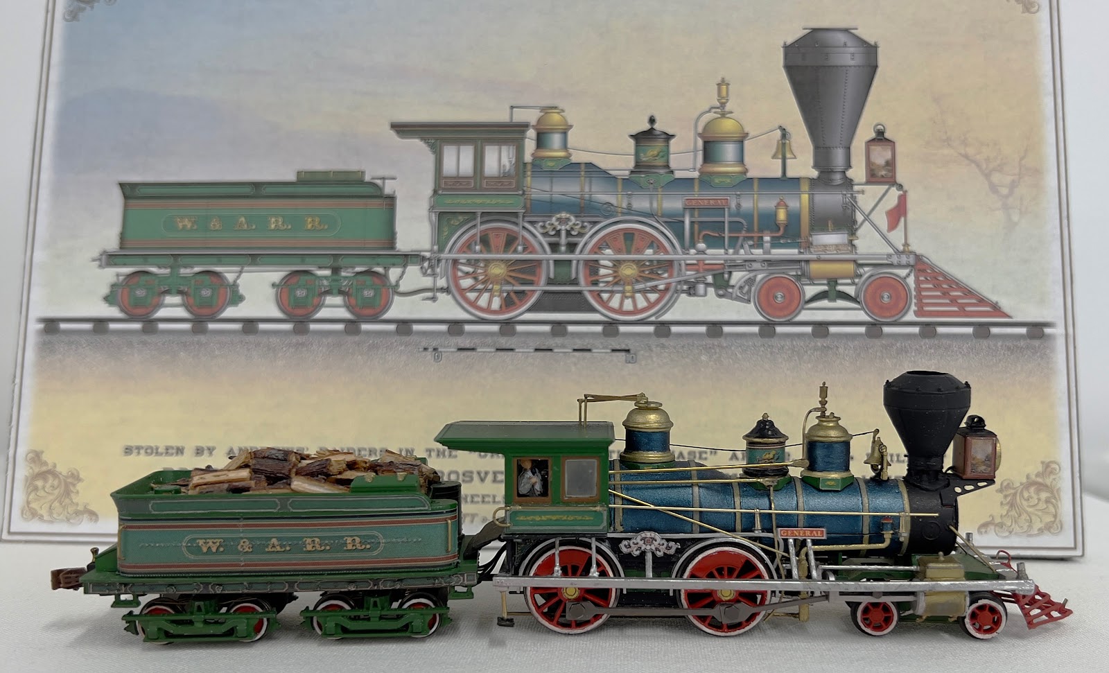
Then last week, George Wallace visited my  layout. George was in the process of liquidating his vast collection of O Scale models. He had a bunch of  civil war era SMR locomotives and rolling stock. He offered them to me. I decided to purchase just one, the General.   Why? Partly to help out my friend and partly because I missed the original model. It is very attractive and runs great. The model arrived yesterday. I placed it on the layout. The model looks great but will need some tuning up. It doesn't ride level, the headlight is broken and headlight box is crooked. I will need to add a sound decoder and keep alive too. Then will come the hard, at least emotionally, part, I need to re-letter it for the USMRR.  

In searching through my records, the following locomotives operated on the Aquia Line in the time period I model, Fury, Fred Leach, Ed Wentz, Victor, Eclipse, Manfred, Osceola, and Lion. I also saw a telegram that mentioned the locomotive Gen. Sickles but I saw no mention of it in the conductor reports. So that telegram might be a garbled message.  Of these locomotives Leach, Wentz, Fury, Osceola, and Manfred seem to be daily work horses with the others showing up less regularly.  I already have locomotives Leach (under construction), Fury and  Osceola. That leaves me Lion, Ed Wentz, Victor, Eclipse, Manfred as possible names. The next step will be to find out which of those locomotives comes closest to the Rodgers General.

According to this roster from 1865 of USMRR engines, the Manfred was from Norris & Sons, Wentz and Sickles were  made by Mason, and Victor was listed as made by "miscellaneous." The Lion and Eclipse are not listed. 

The General was made by Rogers, Ketchum, and Grosvenor. If I'm lucky Lion or Eclipse were made by Rogers. That way I can get the locomotive manufacturer and list of Aquia Line locomotives to match up. Otherwise I will have to pick a name from the list, or make one up. 


The National Capitol Model Soldier Society Annual Show 2021. 


I attended the National Capitol Model Soldier Society Annual Show 2021 last weekend at the Springfield Hilton Hotel. This was their 60th show and first after COVID. There were over 250 models entered from 36 different persons. NVNTRAK was there with a small TTRAK layout.

It was fun to socialize with fellow modelers. I also picked up a tube of new oil buff-able metallic paint from one of the vendors. It can be polished when dried. I am looking forward to trying that on the brass parts of the Leach that I am scratch-building. 

I entered 4 models in the contest and to my surprise, received two gold and two silver medals.   The biggest surprise was that the bust of Diablo got a gold medal. I included it as a lark, as I like the concept of it, but the paint scheme is quite simple. It is supposed to look like an animated stone creature. I did add an LED light in the interior to create a glowing molten look. Perhaps that is what the Judges liked.

The other gold medal was my Aachen Diorama

My personal favorite, Stay a While and Listen,  received a silver medal. The Red Devils vignette also received a silver. I made that vignette several years ago, but gave it a rework this year for the show. 

Model contests are very subjective, so I don't get too worked up over them. But it is nice to receive recognition from your fellow hobbyists for jobs well done. 


January 12, 2021

Compendium of Photos of Engine Leach

 I thought it would be handy to have a single blog post with all the photos I have found of the USMRR engine Leach. John Ott was very helpful in sending some of these to me. The first two I had previously posted on my blog.


The next two are actually the same image, except one is a wide view and one is close  up. 


The last image came via John Ott. Note the circular headlight in three of the images. Only the one image shows a rectangular headlight. Since Leach had suffered battle damage during its career, some parts were likely changed. Also not in the second and last photo there is an odd ring-like part on the rear steam dome.  On some of the photos the lettering on the tender is barely visible.

This photo is not very clear, but we can see the rear dome is partially disassembled. Also
not the fact car loaded with wheel sets. One of my readers pointed out that the connecting crank rod on 
the port side appears to be missing.

The following images are of other locomotives made by NJLW that John Ott sent me. They may share some family traits with Leach. But Leach is the only one with three domes. Leach was also bigger than most other ACW era locomotives. She also had a longer wheel base than most.  


January 11, 2021

More Archives of Civil War Era Photos

Front quarter view image of Locomotive Leach at the UMBC Digital Collection. Note the lanterns
hanging from the light bracket.

In doing some research for an article I am writing, I came across two archives of civil war photos that I had not seen before. Those archives have some images that are new to me. There are not that many photographs of the civil war in comparison to later wars, so when you find some undiscovered images it is a treat.  Especially when one is germane to one of your modeling projects. 

The first archive was at the University of  Maryland Baltimore Campus Digital Collection. They have several photos I had not seen before. But the best discovery for me was the photo of Engine Leach from the front quarter view (see above). The link to the image is here. I did not have a nice clear image of the front of the locomotive. This image answers a lot of questions I had on the front details. This image is now the fifth image I have of this locomotive. The caption at the UMBC archive says this note was hand written on the back, "A Famous locomotive in the Virginia campaigns fought for, taken and retaken, disabled and recuperated."

The second  archive was on website for  The Met, which is the nickname of the New York Metropolitan Museum of Art. They have an on-line collection of civil war photos. This image at the left of Culpepper, VA is part of the collection. I don't believe I have seen this image before. There is the link to the image. I did see some captions that were incorrect, so be careful when you read them. 


January 8, 2021

Update on the Locomotive Build

 I have received several questions on the status of the locomotive build.  I decided to take a break from the locomotive project to work on some other things that I have been thinking about for a while.  But here is where I left off on the locomotive.


A few weeks ago I painted and assembled the parts of the locomotive that I had completed. I used some new metallic paints from AK Interactive in Spain. They are very good. They look like metal but are easy to apply.

As I was examining the model, I realized  I needed to make a lot of changes. In particular, I did not like how I did the crosshead guides. I also need to make changes to the firebox and the interior of the boiler.  The frame needed  modifications to the rear saddle and the back deck. On the inside of the stack, I need to add a lip so the screen will sit securely and not fall into the stack. I needed to correct the rivet pattern on the smokebox. I want to name a name plate holder on the side of the boiler. Most importantly, I need to adjust the location of the hole for the subframe. Somehow it ended up too far forward by about 1/8 inch.

All those changes required that I modify my drawing. But, because of the way I drew it using imported dxf's and joined bodies, making changes was very difficult. This is was because I am not that familiar with Fusion and didn't know about the proper way to set up a file so changes would be easier later.  Fusion uses a top down approach, so each new part references existing parts. If you make changes to a part, the changes bubble through the whole drawing. I was getting a lot of errors as Fusion was unable to implement some of the changes I was making mostly because I did not set up the file correctly. 

So I started the a new drawing from scratch using the proper file layout.  A big change in the design is how the cylinders and cross head will attach to the frame. It will be easier to show later than to explain now. 

 I did about 8 hours of screen time on the new drawing.  It was getting tedious,  and the way Fusion works with my mouse, my fingers were getting sore. To pan you have to push down on the mouse wheel and to orbit you push on the mouse wheel and hold shift. The pressure on my finger from pushing on the mouse wheel was making my index finger sore, so I took a break.  It is possible to reconfigure the mouse buttons and that is something I should look into doing. I am using a nice Logitech MX Master 3 mouse, but the mouse wheel is big and take a lot of pressure to push. I have thought about getting a Wacom tablet. My former Wacom tablet, which was about 10 years old,  would not work with the new computer and OS. 


Anyway, here is a screen cap of where I left off on the new drawing. Note the file structure on the upper left. Hopefully this will make changes easier. I still haven't quite figured out how the timeline in Fusion works. I have learned that doing multiple un-do's using control Z doesn't work in Fusion like it does in other programs. Also, all the parts share an origin, which makes things a lot simpler. My previous drawing did not, and parts were referenced from different origins which made alignment tough. I have to chalk this up to learning pains from teaching myself Fusion360. I am sure an experienced user would have no trouble with this. 

I ordered some brass detail parts made by  Precision Scale for the loco from my favorite shop, Mainline Hobbies. They came in and I did some work assembling them. The light bracket, bell and whistle will work just fine on the loco. I'm not sure about the cow catcher yet. It won't be hard to draw and print a proper cowcatcher if the brass one doesn't fit.  Also, note how the brass parts compare to the painted 3-D printed domes. The painted parts look just fine.  I was able to put a nice shine on the brass bell.  I can always make brass domes on my lathe if I find I want them really polished. 


December 18, 2020

One Day Builds between Printers


Diablo III on the Christmas mantle seems like an appropriate decoration for the year 2020. The glowing eyes are made with 
an LED powered by a battery in the pedestal.

It have been a super busy time in the past two weeks. Since my last post a lot has happened. The big news is that I upgraded to a better 3D printer.  The Anycubic Photon that I bought a few months ago was just not worth investing any more of my time. While it could give decent results, I was getting about a 50 percent success rate. When prints take 6-16 hours, a failed print is a big set back and waste of time. So I ordered and received a Form 3 from Formlabs. It's more of a "professional" grade 3D printer that uses low force, laser stereo lithography. This should make more reliable and better finished prints. Plus, Formlabs was started by 3 MIT Media Lab guys - us Tech Nerds have to support each other. 


Anycubic Photon on the left and Formlabs 3 on the right
I'll talk more about the Form 3 (F3 from now one) later when I have more experience with it, but so far I have had a 100% print success rate

Before I ordered the F3, I sent the locomotive frame stl file to Shapeways for a test print. I did that to evaluate the fit, strength, etc. That print cost about $50 and took about two weeks to get here. Note it was too big to print on the Anycubic Photon.

While I was waiting for the test print from Shapeways and the new F3 to arrive, I decided to work on a few small projects. If you watch Adam Savage's Youtube show called "Tested" you will be familiar with one-day builds. They are small projects that he can build in a day in his incredibly well equipped and stocked shop. He makes replica movie props, scale models, tools, clothing, costumes, and all kinds of things.

So I did some of my own one-day builds. I made some Christmas presents for relatives in my shop, Then, being inspired by Adam Savage, I  made a statute of the title character  from a computer game that my kids and I played, and I still play occasionally, called Diablo III.  Diablo is the evil enemy boss you are fighting in the game.

I made the statue from a stl file I downloaded from Thingeverse. The figure is not exactly the game character, but it was close, and it was free. There are stl files that more closely resemble the game character, but they were somewhat costly. 

I printed the free version of Diablo III on the Anycubic Photon. The prints were not perfect, they had a flaw in the back, but I was still able to use the pieces with some sanding and putty. Since the Diablo character appears to be made from a glowing lava-like substance, I added an LED in the head to light it up (n.b. Diablo has no gender, it assumes the identity of the person it possesses. In Diablo III , that person was a woman. Hence Diablo III has some female features.) To further the effect of glowing lava, I used some florescent paint, which looks creepy in UV light.


With the statute painted and illuminated, I decided to build a pedestal for it. So I went to Woodcraft and picked up a piece of ebony wood for the pedestal. I shaped the wood in my shop. Any excuse to use my wood working tools is OK with me.

So my one day build took two days. But it was a fun diversion. Then the test printed locomotive frame from Shapeways arrived and a day later so did the F3. So back to the locomotive. 


First print of the loco frame on the F3

The test-printed frame from Shapeways looked OK and was surprisingly strong, but it had a few glitches. So, one of  the first jobs for the F3 was to print a new frame with some modifications for the locomotive. I decided to try to print the cylinders and cross head guides as part of the frame. This will make installing the crossheads tricky, but it made the whole frame assembly quite strong. 

The weakest point in the frame is behind the crosshead guide  bulkhead  where the frame splits into two rails going to the rear.  To stiffen this section, I added sections of 1/32nd inch piano wire to the frame. I secured those with 5 minute epoxy. 

With the frame bolted to the smoke box and boiler, the whole assembly is very stiff. 

I am a little concerned about wear in the crosshead guides. If I see these parts wearing I have a few options. One, print a new frame. Two, replace the crosshead guides with nickel silver. Three, reinforce the resin crosshead guides with thin nickel silver wear strips.  

Now to get this painted and add the running sub-chassis. The first sub-chassis I built will not fit in this design. This loco has a longer wheel base and uses smaller drivers.

The white parts were printed on the Anycubic while the 
gray frame was on the F3


December 4, 2020

The Many Pitfalls of 3D Printing

If this is starting to seem like a computer blog, please bear with me. Three-D printing is really applied computer science, so you need delve into such arcane matters. Those of you that follow my blog know that I hate when computers take over my model railroad. That is one of the reasons I model the 1860s. I do not enjoy  wiring and dread the thought of maintaining a large fleet of locomotives with DCC technology. But, I can't deny that technology has made modeling a railroad set in this period possible as there is almost no commercial support. I have embraced computer aided drafting of track plans, laser cutting, DCC, battery power, microprocessors, LED lights, and now 3D printing to accomplish my goals.

So with that preface, let's look at another pitfall awaiting the modeler as he explores the dark, sticky morass of 3D printing. To date most of my 3D printing objects have looked incredibly detailed with nearly invisible layer artifacts. That is why I was puzzled by the facets visible in the first prints of the boiler I made. They required a significant amount of sanding to smooth.

Visible facets on boiler sides 

I decided to see how hard it was to prepare the boiler for painting. I primed it with Rustoleum Filler Primer. I sanded it as described in my previous post.  I used 220-400-600 grits to get a nice smooth surface. Then I sprayed with a coat of Vallejo Black Primer which I had on hand. I don't like this primer as it doesn't seem to self level well, and you can not wet sand it. I don't plan to use it again. 

Paint test on an early version of the model
Next, I sprayed a coat of Future acrylic floor polish to get a nice glossy surface. When that dried, I sprayed  the final coat of Vallejo Natural Steel.  This is not the paint I plan to use for the final model but I had it on hand. The results were good in the areas that I was able to effectively sand. But against the boiler straps (which remain unpainted in the photo), and along the firebox, I could see artifacts of the print process. 

This got me wondering if there was something I was doing wrong in the 3D print work flow that created the facets. After some google searches and checking with the Fusion360 help forum I had the answer.

Non-computer jocks can skip the next two paragraphs. In my Fusion360 workflow, I had been using the "Export" command to save the artwork as a .stl file for 3D printing. For some unknown reason, Fusion360 uses a server to do that conversion. So, you have to send the file over the internet and it sends back the .stl file after about 3 or 4 minutes. This option does not allow any customization of the conversion settings. It is also slow as the file has to be sent over the internet. In this case the resulting .stl file was 75MB.

But, there is a better way. If you right click on the object in the Fusion360 component browser a pop up menu with several options opens up. Buried in that list is the option to "Save as stl." If you select this, another pop-up window opens with options to change the settings of the stl conversion, including the option for a "highest" quality file. The default was "medium" quality. Now that was obvious! (sarcasm alert)

For the small objects I printed so far, medium quality was good enough. But on the large boiler the medium setting was not good enough. So I saved the file as a high quality stl. The resulting file was 550MB, nearly 10 times larger. But it saved it nearly instantly. Win-Win.

So I set about printing the boiler again. After 9.5 hours on the printer I ended up with a much nicer product.  There are no visible printer artifacts as you can see in the photo below.

New boiler print on the highest quality settings
 The frame in these photos is a temporary one made with laser cut MDF. I have ordered a 3D printed part from Shapeways using SLA "Accura Xtreme." which according to their website is "Accura Xtreme is a gray and rigid acrylate-based plastic. It is 3D printed using a large format stereolithography (SLA) printer capable of producing small to large parts with high resolution and detail as well as smooth surfaces with limited layer lines. This material is well suited for challenging functional assemblies with a smooth, injection molded-like surface finish." Seems like a good option for the frame.  If that is not good strong enough or is unsightly, I will pursue other options. Once I have the frame, I will set up the motor and gear box and  try to get it to at least turn the front drive wheel.

In the meantime, I have other tasks to do like make the cow catcher, the cab, many sundry other parts,  and prepare the artwork for laser cutting the rods and fine details. Those will be sent to a commercial laser cutter than can handle cutting metal. 


December 1, 2020

Adventures in 3D Printing

Perhaps that title should read "Mis-adventures." I have been proceeding with 3D printing of many of the parts for the Leach locomotive. As I print, I am learning what works and what doesn't. So I am revising the drawings and doing follow-on prints. Combine that with about a 50% success rate on my prints and the process has been slow. 


Here is the WiP state of the drawing as of today. I am learning Fusion360 as I go, so my progress has been slow.  I frequently have to go to the Fusion360 help site or watch a youtube tutorial on how to do things. 

I made things both simpler and harder for myself by using imported elements from my original Adobe Illustrator 2D file. The Adobe Illustrator elements get imported into Fusion360 as .DXF format. This allows me to use the artwork, so that saves time. However,  this also causes some trouble since I haven't mastered Fusion360. For example, I have not figured out how to get the imported .DXFs to line up with the origin on my existing artwork. So the artwork is seemingly placed at random on my Fusion360 drawing space. Secondly, I have yet to learn how to get different sketches and 3D elements (called bodies) to line up automatically. This is trivial in Illustrator, but not so in Fusion360.

On really annoying thing is how the key combinations in Fusion360 are different than Adobe Illustaor and other 3D programs. I have accidentally moved my objects in Fusion360 when I was actually just trying to pan or orbit the view. This causes all kinds of grief as I then have to manually realign things. I tried using the joints command in Fusion360, but that seems to make things even more complicated. There seems to be no easy way to group items to keep them together. Sketches, bodies and components in Fusion360 all have different ways to align and group. It's very confusing.

Also, I have not yet figured out how the time line in Fusion360 works. When it does what I want, it is sweet. Like changing the diameter of a rivet and all the other like rivets automatically update. But other times, I will change the timeline and things disappear or go wonky.

Converting the Fusion360 drawings to 3D prints has also been a learning experience. It's fairly easy to export parts from the Fusion360 file to a format that the printer can take, which is .STL in my case. But getting that .STL file in a format the printer can handle requires additional steps.You have to use software to add supports and then slice it for the printer. There are several programs that do this. I have been using Preform, Chitubox, Meshmixer, and Photon Workshop. 

Prefrom is Formlabs 3D print slicing software. I use it to get suggestions on how to support and slice an object as its automatic support logic is quite good. But it only exports to Formlabs printer formats. So I can't use it with the Anycubic Photon that I own. 

Once Preform gives me some ideas, I use Chitubox to set up the supports. If the file has "errors" they can sometimes be fixed in Meshmixer. Meshmixer has a lot of power to do other things too, like modifying or  drawing your own objects, but I haven't explored it that much yet.

Once Chitubox is done, I have to run the file in Photon Workshop to save as a .PWS format as my printer requires that type of file. 

I have experienced several failed prints usually stemming from inadequate supports. But I also had 2 leaking vats and other sundry problems. 

WiP so far. The frame is a laser cut MDF for fit only. The actual frame will be either 3D printed, or made from brass. The cylinders will be 3D printed in brass.

Anyway, enough boring 3D print nerd stuff.  I have been able to print the smoke stack, cylinders, boiler and firebox sidewalls, and some of the dome.

I tried printing the frame on the Anycubic Photon, but it was too large for my printer volume and would not print reliably. So I sent that out to Shapeways to have them print in SLA plastic. I selected that material as it has a faster turnaround than doing it in metal. I want this first 3D printed frame to test the fit of all the parts. Once that frame arrives, I'll add the sub-chassis and see if I can get it running. Then I can add  the rest of the parts. At that point I'll evaluate if I can proceed with a 3D printed frame, or built by hand with brass stock, or have metal parts laser cut by an external service. 

Some of you have commented on tolerances and shrinkage of the printed parts. Because of the compensated sub-chassis design I am using, all of the tolerances on the parts I have 3D printed so far are not critical. The key issues is making sure the distance between the axles  is precisely the same as the length of the holes in the main drive rod. Those parts will not be 3D printed. 

3D printed stack with laser cut and brass details
I am pleased with the stack, smoke box and boiler print quality. The stack is a combination of 3D printing, a brass mesh for the cinder screen, a laser cut cinder screen support, and a section of flat brass for the screen latch.

The cylinders came out nice too, but I am not sure they are strong enough to use in the working model. I plan to have these 3D printed in Shapeways brass, which uses 3d prints to make a lost wax mold to make actually brass parts.


Sanding and polishing the boiler surface
I am surprised at the strength of the boiler. It is quite sturdy. The 3D boiler had some print layering visible, but I was able to sand those away after a coat of filler primer. The next challenge is to try to paint it to look like Russia Iron.   I ordered some BareMetal foil to try out.

The 3D printed boiler may actually work better than the brass tube I was planning. The reason is that the brass tube is relatively heavy and will raise the center of mass of the locomotive up and to the front. By using a lighter material that is hollow, I can add weight lower and might be able to get better balance. I am hoping that will put more weight on the drive axles to increase tractive effort that the locomotive can provide. 

I need to change the method of attaching the domes to the boiler. I used Fusion360 to match the boiler curvature on the bottom surface of the domes. But, the dome parts have to be supported on that curved face to get a clean print. That means I need to sand away the support residue which can make it hard to precisely match the curve. A through hole that is the diameter of the  dome with a matching internal support in the boiler might be better as I would not have to sand any visible surfaces.