A journal following the history, design, construction and operation of Bernard Kempinski's O Scale model railroad depicting the U. S. Military Railroad (USMRR) Aquia-Falmouth line in 1863, and other model railroad projects.
©Bernard Kempinski All text and images, except as noted, on this blog are copyrighted by the author and may not be used without permission.
-----------------------------------------------------------------------------------------------------------------------------------------------------------------
Showing posts with label Artillery. Show all posts

August 2, 2022

The Lee-Brooke Rail Gun


In November and December 2012 I built a model of the Lee-Brooke Gun. Since the time I wrote about my build, I have received several requests for more information about this gun.  I decided to consolidate my notes into one blog post to make reference easier.

This was the first ever railroad artillery piece. It had several names including the Land Merrimack or Dry Land Merrimack. Now I call it the Lee-Brooke gun based on Dr David Schneider's research. I have written about my model of this gun in several blog posts. 


Lee-Brooke Railway Gun


Below are the plans that Edwin Alexander published in his book on Civil War railroads. The plans are pretty good, but you may need to adjust some of the details of the front glacis based on inspection of the actual photos of the gun.  He did get the scale wrong. The wheels are about 28 inches in diameter, not the 33 inches he used in his drawing.  But the overall proportions are correct. So just scale it so that the wheels are 28 inches.


Also, his caption states the the gun is a Parrott. That is not correct. It is a 32 pound Brooke Banded Rifle. That was a fairly rare cannon but a few survived. There is one at the Washington Navy Yard. It was captured at Fort DeRussey in Louisiana. See http://www.fortderussy.org/artillery.html for more info. If  you look at the photo at the bottom of this post you can see that the muzzle of the gun has a swell and moldings. 

I did visit the US Navy Yard in Washington, DC to measure a surviving copy of the rail gun. I used those notes to build my model. Alas, the notes with my measurements were lost or thrown out since I recall they got oil stains and grease on them when I was making the model.  I decided to measure the model and reverse the measurements so that others can use them in constructing their models. See below. Note that the cascabel of the gun at the Navy Yard is slightly different than the gun used in the railroad gun. 

The carriage of the gun is also a unique design that I could not find used anywhere else. This is my interpretation of it. 


Here is a view without the side armor


I also suggest you get a copy of Dr David H Schneider's article in Civil War Times, Feb 2011 for a more thorough description of the railroad gun's provenance. 


Note that the muzzle of the gun is not smooth like most Brooke naval guns but has a swell and muzzle moldings.

Animated gif from stereoscopic photos


February 13, 2022

Rock Me Some Wagon Wheels


...with apologies to Bob Dylan, to finish up the cannon I had been working on, I drew some 14-spoke wheels. I had some artwork for wagon wheels from Gerry Dykstra, but that was not in a format I could edit.  So I decided to draw my own. To get the model as precise as I could, I went up to Fort Ward to measure the cannons they have in the restored bastion. One of their  guns is a very authentic replica of a 6 pound James Rifle. 

I was able to get detailed measurements of the wheels. The hubs in particular were quite interesting with a cove on the inside and an ogive on the outside. Also, I measured the amount of dish in the wheel. It was only 2 inches, but that is an important feature of wagon wheels from this era.

I also measured the 24 pound howitzer they have on site. It is slightly bigger that the 6-pounder but only by about 4 percent. 

While I was at Fort Ward I stopped by the Museum and visited the replica of the officer's quarters. I took a panorama of the inside of the officer's quarters. I need to recreate something similar on my layout. I plan to detail the upper story of the Provost Marshall office. So this photo will help guide me. I also had a nice chat with the museum director as she and her colleague were wondering why I was measuring their guns.

Interior of officer's quarters for detailing ideas. Looks cozy.


Telegraph System


Amby continues to make amazing progress on the telegraph system, He now has all five base stations done. 

I think he has been having fun with them as he sent me this image of the dot code on his oscilloscope.  I was playing around with speeding up the code. I think it might be a tad easier to listen to at about 25% faster than what we have now.  It remains to be seen if we will be able to change that in the software.


 It is time to begin wiring the dispatcher's control station. That will be built into the cubby hole section of the dispatcher's desk. 


When I built that cubby hole I was inspired by the field desks that civil war officer's used. It happens that the museum at Fort Ward has one of those on display too.


Each individual station will be adorned with simulated brass plates that I printed on my 3D printer. I now need to finish painting them. 


February 9, 2022

Cannon Fever


It's winter and we are cooped up. I have cannon fever. So, I drew a 1/48th scale 3- inch rifle, a common Union field artillery piece in Fusion 360 today.   I left a few details off the drawing. They will be added with the photo etched parts I have on hand.


Laser cut cannon with 3D printed limber

If you recall, I already have 1/48th scale cannon made with laser cut parts, cast metal barrels and photo etched detail parts. They look good, but require some assembly. If the 3D files work out, the 3d printed cannons will have much simpler assembly. 

Combined with the 3D printed limber I made a few months ago, I will be able to begin field artillery batteries as scenery items for the layout. If the test prints work out, the Aquia Line will be brimming with cannon soon.


To answer the question in the comment below, here is a table of cannons commonly used in the civil war.


Decal artwork

Last night I did some graphics work for Brian Kelly. He lives in our area and is modeling the C&O. He wanted a decal for a milk truck on his layout. But, all he had was a rough photo of the company's logo from a cloth patch. He asked me to redraw it so he could make a decal. I am including it here in case anyone else might need it.  You can re-size it as needed when you print the decal.


September 24, 2021

Getting Limber


Limbers are like the pick-up trucks with a tow hitch of the Civil War.  They were used to haul cannons, caissons, battery wagons, and even a coffee wagon.  We have several period photos showing rows of limbers and other carriages lined up at wharves and railroad depots as in the scene above at City Point, VA.

I had perviously made cannons using cast metal, laser cut wood, and photo etched brass parts. I ordered some 3D printed limbers to go with the cannons from a vendor in Europe. Unfortunately, when those parts arrived, they were not printed at the correct scale. They were about 20 percent too big. Trying to redress the problem with an overseas vendor was not practical. So I still needed some. 

View of the limber I drew
A few months ago, Gerry Dykstra, from the ACWRRHS Group,  sent me a copy of the 3D print file he drew for a battery wagon. Each artillery battery had one battery wagon along with a battery forge and 4 to 6 guns . 

It was a simple matter to scale the file to 1/48th and print on my 3D printer. The model is very nicely done. But, he did not include a limber. He did include a limber pole, an iron rod used to support the tongue of the wagon when the limber was not attached.  However, I believed I needed a limber to accompany it and my artillery pieces.

I decided to draw one myself. It is not that complicated a vehicle and it would be good practice for me in Fusion 360. Gerry already drew the wheels, so it was fairly simple. See the second  drawing. 

Gerry's battery wagon on top with
my limbers and cannon
I printed a test model. It need just a few modifications and it was good to go.  Then I printed  7 more.  

I decided to not include the ammo chest handles in the print. I will add those with wire. But I did include the locating holes to simplify drilling the holes.

This was a fun project that didn't take too long. Now, with limbers taken care of, I need to make the supply wagons. I started making a supply wagon using my cast wheels and laser cut parts. But I think a 3D printed version would be better able to show the detail on the wagons such as the tiny rivets and bolts.


April 4, 2013

The War Came by Train - 1863

The B&O Railroad Museum had a ceremony today to officially open the third year of their five-year exhibition on the Civil War called "The War Came by Train." Courtney Wilson, the Executive Director of the B&O Railroad Museum, mentioned that interest in the civil war and this exhibit has lead to a resurgence in interest in the museum. They get more than a quarter million visitors a year.

This year the museum jointly celebrated with the state of West Virginia, which is also celebrating its Sesquicentennial -  150th Anniversary of Statehood.  Several officials from West Virginia were on hand for the ceremony. Dan Toomey and Richard Wolfe gave brief speeches about the significance of the B&O in the formation of the state of West Virginia. Here were some interesting facts they mentioned.


  • The reverse side of the West Virginia state seal has an image of a B&O Railroad train.
  • The first Union soldier killed in action by a Confederate soldier happened in what is now West Virginia at a fight over a bridge on the B&O.  
  • The eastern panhandle of West Virginia, the part of the state that gives it such a distinctive shape, was a result of the Union government wanting to keep the B&O RR in the new state of West Virginia and out of the rebelling state of Virginia. Whether West Virginia could remain a state was disputed by Virginia after the war and was settled by the US Supreme Court.

The West Virginia folks brought along representatives from several gourmet shops and business in West Virginia with samples of their food and beverages.

In the gallery the rail gun models I built for the museum and the ones I loaned were on display. If you visit the museum, which I recommend, please give them a look.


The caption on the card is incorrect- this is a 1:32nd scale model on loan.


January 28, 2013

Another Land Merrimack

I received a note from Greg Vigle, a collector of model artillery. He sent me some photos of an model of the Land Merrimack rail gun he bought from an estate sale. Here is what he said,


By chance I happened to find photos on the military railroad page of a remarkable model that you recently constructed of the famous Petersburg railroad cannon. I was utterly astounded, especially given the timing, to find this, because I very recently acquired an almost equally remarkable model of the same piece, made over 25 years ago! I am attaching a scan of two photos of this model, taken by the maker. The scale is probably about 1/24, with the entire model about 11 inches long
              The man who made it was named Joseph Sckripkunas, he was a former machinist who specialized in making incredibly detailed models of cannons. He made over 300 over a 30 year period, and was very well known in the model cannon world. I acquired a substantial number of his remaining smaller models last year from a friend of his who was the executor of his estate, he passed away early last year. This particular model was apparently one of his most prized, with good reason.
              Like you, he had only the two known photos to go on, plus similar amounts of additional historical information (he was an expert on cannons in general). But, he most likely only had access to photos reproduced in books, as opposed to high-res 8x10 prints (I now have the latter, of both of the known photos). 
It looks like a section of G gauge track under the model, so the scale is probably close to 1/32 assuming it was built on standard gauge track.

It is different from my model in some respects, but overall, it is a very attractive model.

Thanks Greg for sending the photos and story.


January 22, 2013

Rail Guns Delivered

Dan stands by one of the exhibits.
I delivered the model rail guns to Dan Toomey at the B&O Museum.  Dan is the curator in charge of designing the War Came by Train Exhibit at the B&O Museum. The exhibit changes each year to reflect the major events of that year 150 years ago in the ACW. The rail guns will be part of the third year exhibit.

The second year the exhibit focused on the Invasion of Maryland and the battle of Antietam, especially the aftermath in treating the casualties. Note the hospital car models behind Dan.

I also had the honor of buying the first copy of Dan's new book titled, "The War Came by Train -  the Baltimore and Ohio Railroad during the Civil War." It was hot off the press and Dan was graciously enough to sign it for me. I will do a detailed review once I have had a chance to read it. But in flipping through it I was excited to see it is not a dry economic description of the railroad, but a detailed account of the people, battles, equipment and operations of the railroad. There is a remarkable picture in it that I have never seen before of several B&O engines in front of the hotel in Grafton, WV.  I look forward to reading the book.

Dan gave me a  brief tour of  the museum to see what is new. The Mason is out getting a boiler refit, so it was replaced with a restored Camel engine.  It is a beautifully ugly beast -  resplendent in its red wheels and trim. I failed to get a picture of it. Doh!

Saying good bye to Dan, I drove to M.B. Kleins hobby store, now in Cockeysville, MD. I picked up some basic supplies, though MBK doesn't have a good supply of scratch building materials.

I purchased two new colors of the Woodland Scenics fine-foliage, light green and olive green, to test against the backdrop. I can't decide which color is best.

 After dinner I proceeded to work on the Truss bridge. I realized that the trusses visible in most of the photos we have were not pin-connected like my earlier arched truss, but "standard" Howe Trusses with counter braces and cast iron pockets for the diagonal members and wrought iron rods for the tension members. Note that the diagonals are doubled in one direction and single (the counter brace) in the other.
It took several hours of drawing to redesign the parts, but once I cut them on the laser, assembly proceeded quickly (including the 828 NBWs!) I need to finish the stringers, ties, rail and upper truss and it will be ready for placement on the abutments, which also need to be made.

In placing the bridge, over Muddy Creek it looks like we need to push the left abutment back about one more inch. That is easy with the foam construction we used.

I also realized that I have half of the diagonal bridge members reversed in the model. In a Howe truss the doubled diagonals should be symmetric to the vertical center line. So three panels are one way and three the other.

I laid them all out the same.  I hope that will not be too hard to fix.


Finally, to wrap up a big day, Andy at Train Troll sent me some photos of the packet boat that will be on the left hand part of the layout. This is an HO scale model of a scow-hull towboat that he will scale up for the O Scale packet boat. It is very similar to the Clinch that we decided to use on the layout.


January 1, 2013

B&O Ironclad Car -- Take 2 (or 3 or 4?)

I was not happy with the earlier model.  So I tried again. The armor should be railroad iron. So it should have a "Tee" rail profile, not a rectangle. I was using code 55 rail to simulate the armor, which is close to the scale size, but is very fine.

I tried several techniques to secure code 55 rail to the sides of the car to simulate the iron armor. On the fourth try I decided to use two-sided transfer tape. That make sticking the iron bars easier to position and reposition if necessary. It also prevented glue globs from showing between the rails. I used the laser to engrave a set of lines to help in the spacing. Even with that the rails did not line up perfectly, but I think it helps the model.

The two finished cars compared. A couple others ended up in the trash.
The transfer tape is quite permanent. The rails are secure enough, especially for a static model.

As for colors, we don't know what they actually were. The dark gray armor on freight car red looked good to me.

So this is the version that will go to the B&O Museum. The earlier version will go on my layout for escort duty.

A slightly revised rear end.

The business end with the gun port cover. The cover was operated by a lever inside the car.

December 25, 2012

B&O Ironclad Cars

I started building 1/48th scale models of the B&O Ironclad and Rifle cars.  These models are destined for the B&O Museum collection.  I am working with Dan Toomey of the B&O Museum to try to make these models as accurate as possible, but given the limited and conflicting information we have about the cars, much is educated guess work.  For example, there are several descriptions of an engagement where one of these cars was destroyed. Each account has different descriptions of the car and its construction. Most of them are summarized at this web site . It's is hard to know which one is right.

The cars are described in Alan Koenig's dissertation, "Ironclads on Rails: Armor Returns to the Battlefield, 1861-65. This was our main source as it cites several statements from the builders, as well as  observers that saw the car in service or after it was destroyed.

The ironclads are also mentioned in Robert Hodges, Jr.'s book, "American Civil War Railroad Tactics." The latter includes an artist's concept painting of what the cars may have looked like as no known images of the cars have survived.  While we agree with the overall look of the cars in the painting, there are certain details we will change.

The drawing shows our interpretation of the cars. The approach we used is to assume they started with standard boxcars and added the armor as an applique. These cars were built quickly, so it seems likely they started with existing parts if not whole cars.

According to Koenig, one source says the armor was mounted on a 45 degree angle. That is possible on the front of the car, but not possible on the sides as it would make the car too wide. So we made the side taper more vertical.

Koenig lists one source that states the rail was "T" iron, while another just says "railroad iron." We elected to go with "T" iron, in the form of code 55 rail, which works out to 2.6 inches in full scale. At this point most major railroads were installing 60 to 70 pound per yard rail on their mainlines, which scales down to about code 90 (0.093 inches inches tall). So the rail on this car represents lighter rail that was either destined for yard use or was retired. I had a bunch of code 55 on hand, so I used it.

Is code 55 reasonable? Yes, because heavier weight rail would have overloaded the 10 ton capacity of the car,  which was typical of a box car of the civil war era on two trucks.  The table illustrates that at 30 pounds per yard of rail the car would weigh about 10.2 tons loaded with crew, gun and ammunition. Even rail at 40 pounds per yard would have overloaded the car by 30 percent.
Heavier 60 or 70 code rail would have seriously overloaded the car. (Note that the number of rails per side for larger weight rail would be less than shown here as the the heavier rail is also wider. But the weight increases with the cube of the size, so the weight gain will out-pace the width related savings.)
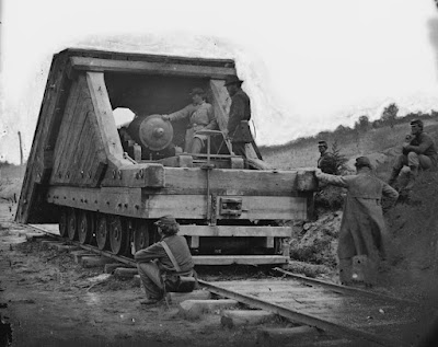
"T" Rail added by the crew to protect the casement corner on USS Cairo

Some sources say the rail was spiked on, but Dan believes that it was bolted. I used the railroad T armor on the restored USS Cairo as a guide for how such rail would have been bolted on. In the case of the USS Cairo, the rail was bolted with the flat side facing out. I reversed it on the car as it was too hard for me to get the code 55 rail to look correct in that configuration. It would not lie flat as I assembled it.

Most sources state that the cars were equipped with one gun each, mostly small mountain howitzers, but one had a 6 pound brass smoothbore.  The first versions of these cars had cannon mounted in the vehicle suspended from the roof with a series of ropes. But later versions used standard field carriages as we show here.

There is a gun port on the front of the car. The artist concept in Hodge's book shows gun ports and cannon pointing out the side, but the car is too narrow for the standard field cannon to fire to the side. So there is no point to have gun ports on the sides, though there may have been observation ports. We elected to include 3 loop holes on each side instead of additional gun ports.

These cars were operated in sets. An armored train would have ironclads on front and back, with rifle cars between the ironclad and the locomotive. So a gun pointing out from each end of the train might be effective in covering the area around the train, especially if the gun could cover a 60 degree arc from its embrasure.

The gun port was reported to be 6 inches square, but again that is unlikely as such a small size would not allow the gun to defect or elevate very much. The gun port must be a bit bigger. One source, Deffinbaugh, claims he found the gunport of the destroyed car and that it was a solid piece of iron.

The last puzzle was the rear of the car. Again according to Koenig, one source says the rear was also sloped with an embrasure for a gun. But most other sources say that only one gun was mounted in each car. If you put a 6 pounder smooth bore on a standard field carriage on a rail car that can travel along standard gauge tracks, there is no way the car can be wide enough to turn the gun around inside the car.  So one gun cannot serve both gun ports.  It seemed impractical to me for the car not to have a decent size access door, so I added one to the rear.

One of the problems I have noted with some artists' concepts and drawings of artillery mounted on flat cars is that they make the gun carriage too small in relation to the car. The drawing above shows both the gun and car in the same scale.  As you can see, a 6 pounder on a standard field carriage just barely fits in the car. There is some room to deflect the cannon right or left to aim, but firing off the side is not possible.

We welcome your comments or ideas. The famous ship historian and modeler Howard Chapelle once said words to the effect that you should never build a model until you have all the information you need, as others that view the model will not know where you guessed. (for more of Howard's argument see this link.)In this case, we recognize that the information is sketchy about these cars and do not claim that this is a 100 percent accurate representation of the car, but the best we can make.  We hope you enjoy it.


December 20, 2012

Rail Gun Encased

The Land Merrimack posed on my O Scale layout.
I added a diorama pedestal base and acrylic dust cover to the rail gun model. The base is a solid plank of cherry that I cut and routed into a base. It matches the base for the Dictator diorama. I still haven't perfected the acrylic case technique yet, as I got a glue stain on the top surface. But it will serve the purpose of protecting the model from dust and fingers.

The section of track is code 100 rail on hand carved poplar and basswood ties. I added some grass tufts and various leaf and pebble texture to the soil. All it needs is a laser cut name plate and it is ready to display. I haven't decided if I should add a figure to the diorama. It might help provide a sense of size and scale. The model is built to 1:32nd scale.


December 13, 2012

Rail Gun - Finished


I finished up the remaining details on the rail gun. I replaced the coupler on the rear. The first one was too big.  Since I laser cut the parts from 1/16th inch acrylic, it was a simple matter to reduce the height of the center part and and reinstall it. The nut detail is actually engraved. The coupler simply is glued to the wood frame.

The brake wheel hangers were the next challenge. I made the parts from 0.020 inch strip brass, a .042 inch brass rod and an etched brass wheel from my spares box. To fashion the parts I used my drill press with an x-y table to drill holes in a straight line. Then I used a new sharp  file to shape the parts. I secured the parts to the model and then added NBW details with CAA. I added a cast white metal gear to the shaft to represent the locking pinion.  To simulate the pawl, I added a small silver of wood.

I had to use brass for the parts  because the next step involved soldering the brake chain to the wheel shaft and the brake linkage on the truck. With everything soldered up, I tested the brake mechanism. It does work, though it would need some adjustments if this were to be an operating model.

Next I added an elevation wheel to the gun (not visible in these photos). I also mounted a small rod on the bottom   front of the gun carriage and added a wood strip with an iron strap on the rear. This allows the gun to deflect a limited amount in the casement while also tilting the gun forward. The tilt allows the gunners to run the gun out for firing, while the up slope helps absorb some of the recoil.

Next I must build the base to display the gun, and an acrylic case to protect it.


Having studied this gun, I am convinced that it was built solely as a weapon to counter other rail mounted iron clad guns. The heavy 32 pound cannon is impractical as a field weapon against mobile infantry and artillery targets. The limited traverse also hinders its use as a general field piece. The heavy armor only on the front meant that they did not expect it to be engaged from the sides.

To my mind the design of this gun supports Dr. Schneider's thesis that this was the "Dry Land Merrimack" that Lee had Brooke build for the Peninsula Campaign in 1862. They built the gun as a response to reports that the Union were also developing an ironclad  railroad gun. The Lee-Brooke gun was used once, probably found impractical as the Union did not have a matching railroad ironclad, and then retired to a siding, where it was discovered a few years later by Union soldiers.