A journal following the history, design, construction and operation of Bernard Kempinski's O Scale model railroad depicting the U. S. Military Railroad (USMRR) Aquia-Falmouth line in 1863, and other model railroad projects.
Amby stopped by on Monday to help solder feeders. He was able to get all of them done while he was here.
Meanwhile, I was working on the bridge abutments and trestle bents. I covered the foam abutments with plastic sheet embossed like stone. I used CAA and baking soda as a gap filling material. Once the abutments were primed and painted with a dark gray, I temporarily installed them in place.
Then I used a 4-ft level to ensure that the stringers were straight. The bridge is on a grade so the level is not necessary. I just need the straight edge. I must have deflected the stringers earlier when I placed the weights on them as all the trestle bents needed some shimming to fit. I'll probably build the bridge upside down and them shim under the sills as necessary.
Paul Dolkos stopped by to inspect our progress. We gave him a demonstration of the telegraph system. Amby pushed the station code buttons while I acted as dispatcher and translated the messages.
Afterwards Paul had a bemused smile on his face. I couldn't tell if he was impressed or just thought we were crazy. Amby said he wants to try dispatching during an op session.
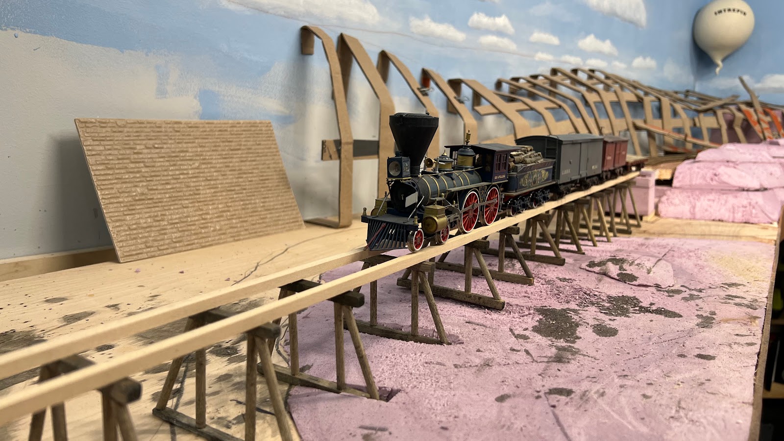
We returned home from a great visit to see my granddaughter and her parents in Alabama. I had several other projects to take care of before getting back to work on the layout. Today I was able to build all the trestle bents for the low trestle over Mueller's Creek.
I started the bridge by making the abutments from pink styrofoam. I used my miter saw to cut the core pieces and a razor saw to cut away the ledges for the bridge stringers. The abutments will be covered with stone plastic sheet by Ratio models in the UK. I used that plastic stone on my other abutments and it looks great.
Next I added the stringers and trestle bents. In my first attempt I used 3/8 inch square stringers and ¼ inch trestle parts. After making 5 of those bents I decided the trestle looked too beefy. So I swapped out the 3/8th stringers with ¼ inch. I replaced the ¼ inch posts with 3/16th inch dowels. I think this spindly look is more appropriate for ACW era bridges. The 3/8th stringers were pine while the ¼ inch ones are basswood. The grain on the basswood is much more in scale than the pine, especially after I embellished the grain with coarse sandpaper and razor saw.
This was tedious work.
I had to make each bent individually as the ground below the trestle is not flat. In addition, the bridge itself is on a grade. So each trestle bent had to be made to fit the intended location. I did not worry too much about variation between the bents as the prototype bridges had a very ad-hoc look.
I pre-stained all the pieces before assembly. I made a crude jig to glue the vertical posts both joists. But each diagonal I measured and cut by hand.
The plastic sheet stock for the abutments is visible behind the bridge,
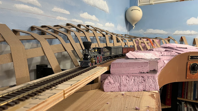
Eeet ees ba-loooon! The plywood bridge and flex track have to be replaced.
I finished laying track at Falmouth this morning. The next step is to remove the flex track and plywood that is currently standing in for the long trestle. Then I can start building the actual parts of the bridge. But before I do that I need to decide where the abutments will be and how they are made. I assume that the original abutments were built by the RF&P so they will be stone.
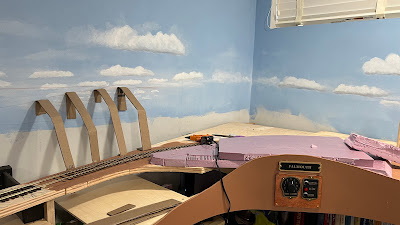
The terrain in this area is somewhat complex. The trestle cuts across a bend in the creek. The south end of the bridge is especially hard to visualize. So I decided to add the basic terrain shapes there first. Once they are established that will determine where the abutments will be precisely located.
In the foreground I used pieces of foam. I used cardboard web for the hill in the rear. That's too big of an area to try to use foam.
I tacked the balloon on the wall to get a look at how it will appear. It is kind of a scene stealer. The final vignette will show the ground crew getting the balloon ready for a flight.
I did use that piece of wood I was saving for 10 years just in case I needed it. But I'm getting ahead of myself. I have been laying and spiking track pretty diligently in the past few days. I now have all the turnouts and almost all the track installed. I just need to add one engine storage track off the turntable and to replace the flex track on the bridge with hand laid track and I'll be done with track. Yes, there will still be several thousands spikes to go but the track will be useable.
The last turnout is installed
With the track done, the next step was installing the turntable. I am reusing the turntable from the old Falmouth. I was able to disassemble it and save it. The trick was finding a place to fit in the new plan particularly to avoid the benchwork. I had to work around the Ikea legs and a joist that was screwed to those legs. I also did not want the electronics from the bottom of the turntable to interfere with the view of the TV under the benchwork. I decided to install the turntable at the far left end of the lead to the engine terminal. There will be just one storage track and that is a reverse move off the turntable. That arrangement spreads the engine service facilities along the turntable lead. I think it looks good and allows me to access the turnout switch stands behind the turntable lead without interference from the water tank or workshops. It also makes the run to the turntable longer.
I knew the wood scraps would come in handy.
To use the existing turntable base I had to cut the plywood the turntable was formerly mounted on. This was tricky as the existing electronics for automatic reversing and hub for the turntable extended below the bottom of that piece of plywood. So I could not just place the base of the turntable on my MFT and cut away. Instead, I set up my saw horses and used some scraps of plywood that I have been saving for years for a job like this. They raised the plywood base off of the deck and allowed me to use my track saw to cut nice straight lines to trim it. I knew those wood pieces would come in handy!
Fitting the pit around the legs and joist limited my choice of possible locations for the turntable.
Next I had to cut the hole in the existing plywood bench top for the turnable. I aligned everything as precisely as I could and drew lines for the center line of the track. I took care to avoid the Ikea legs under the table top. I drilled a half inch hole on the plywood table top to accept the turntable axle. Then I used the turntable spinning in that hole as a trammel to mark the circle necessary for the pit. I added a half inch to the radius to allow room for the wooden retaining wall. Then I used my Carvex saw with a fine blade to cut the circle.
Instant turntable
I had to notch one corner of the turntable base to fit around the Ikea legs, but the turntable popped right into place. Four screws pulled the turntable tight and secure. I must say it was gratifying seeing the turntable installed in the pit and even with some existing ground cover on the pit floor.
I installed railroad ties around the pit wall to act as a retaining wall. The ties give the pit a rough and temporary look perfect for a military structure.
I put a quick coat of paint on the fascia and its starting to look like something. The new Falmouth with its long sidings and greater track capacity should allow more involved operations. Plus, I think it is going to look really cool.
The installed turntable, painted fascia and some ground cover looks good.
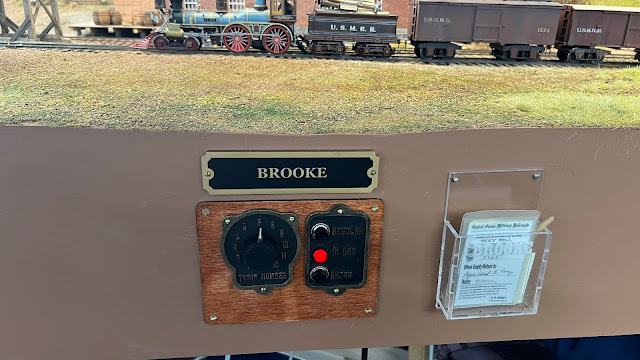
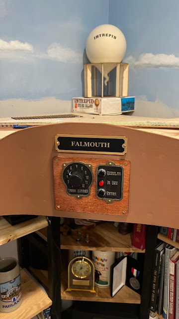
Amby stopped by this morning to help finish the installation of the telegraph system. He ran the last cable to Falmouth while I finished building the panels for Brooke and Falmouth. All went fairly smoothly except for me accidentally installing the Falmouth panel at Brooke. That was an easy fix.
Location of telegraph station at Falmouth
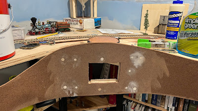
The Falmouth telegraph station is mounted on the curved section of the fascia near the balloon camp and north of the turntable. I needed to reinforce the curved fascia with a scrap of 3/4 inch plywood to flatten it out and stiffen it.
First I wet the fascia to allow it to bend more easily. Then I glued and screwed the plywood to the fascia. After a few hours it was ready for cutting the hole with the jig saw.
In between putty and paint drying I continued to spike track. Amby also took a crack at spiking. I did not sense a lot of enthusiasm from him for the task. I am not sure he will volunteer for more of that activity.
Special thanks to Amby, Seth, and Steve for their help in getting this system designed and built, installed and tested.
With the telegraph done, now we need to get the track finished. Just about 5,000 spikes to go.
I restarted work on the Aquia Line after a long break. I am scheduled to host op sessions for the ACWRRHS and an open house in October for MARPM. So I need to get the track finished and operational before then. Hopefully I can get some scenery and the bridge built by then too.
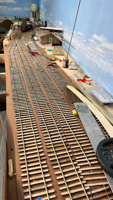
The long sidings at Falmouth take a lot of spikes!
I have been spiking track over the past 4 days. I have just one turnout and the turntable to go before all the track is laid. I don't spike every tie as I am initially laying the track in case I need to adjust things. Once the track is operating satisfactorily, then I go back and drive 4 spikes in every tie.
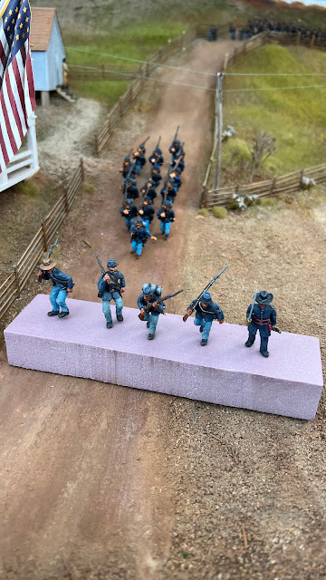
On Saturday Jack Thompson stopped by to do exactly that. He spiked about 3 feet of track by the balloon camp. He also dropped off some figures he painted for me. Jack is an excellent figure painter. He is also a model railroader and a dedicated re-enactor. I met him through my association with the National Capitol Model Soldier Society. I was a member many years ago and recently restarted attending the meetings.
He was the one that suggested another file of men in the squad by Brooke. ACW units usually marched in files of 4. I have my other units on the layout in 4 files, but I didn't have enough figures painted to do that here. Thanks to Jack for volunteering to paint the figures to bring them back into regulation. Plus he did a great job.
I was a little rusty in installing the turnouts. Plus I restarted with a double slip. But I got it working OK with just a few foul words. Hopefully the last turnout will go smoothly.
I plan to reuse the turntable from the previous Falmouth, so hopefully that will also go smoothly. Fingers crossed.
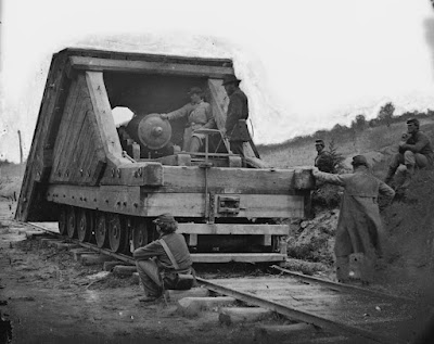
In November and December 2012 I built a model of the Lee-Brooke Gun. Since the time I wrote about my build, I have received several requests for more information about this gun. I decided to consolidate my notes into one blog post to make reference easier.
This was the first ever railroad artillery piece. It had several names including the Land Merrimack or Dry Land Merrimack. Now I call it the Lee-Brooke gun based on Dr David Schneider's research. I have written about my model of this gun in several blog posts.
Below are the plans that Edwin Alexander published in his book on Civil War railroads. The plans are pretty good, but you may need to adjust some of the details of the front glacis based on inspection of the actual photos of the gun. He did get the scale wrong. The wheels are about 28 inches in diameter, not the 33 inches he used in his drawing. But the overall proportions are correct. So just scale it so that the wheels are 28 inches.
Also, his caption states the the gun is a Parrott. That is not correct. It is a 32 pound Brooke Banded Rifle. That was a fairly rare cannon but a few survived. There is one at the Washington Navy Yard. It was captured at Fort DeRussey in Louisiana. See http://www.fortderussy.org/artillery.html for more info. If you look at the photo at the bottom of this post you can see that the muzzle of the gun has a swell and moldings.
I did visit the US Navy Yard in Washington, DC to measure a surviving copy of the rail gun. I used those notes to build my model. Alas, the notes with my measurements were lost or thrown out since I recall they got oil stains and grease on them when I was making the model. I decided to measure the model and reverse the measurements so that others can use them in constructing their models. See below. Note that the cascabel of the gun at the Navy Yard is slightly different than the gun used in the railroad gun.
The carriage of the gun is also a unique design that I could not find used anywhere else. This is my interpretation of it.
Here is a view without the side armor
I also suggest you get a copy of Dr David H Schneider's article in Civil War Times, Feb 2011 for a more thorough description of the railroad gun's provenance.
Note that the muzzle of the gun is not smooth like most Brooke naval guns but has a swell and muzzle moldings.
I recently acquired a Canon R7 mirrorless digital camera with the kit 18-150mm lens. I purchased this camera as my former Canon 70D was over 10 years old. While it was in excellent condition, the newer cameras have surpassed it in technology. When I read about the Canon R7 I realized it had some great features for model railroad photography, particularly the automated focus bracketing feature and high resolution. I also was impressed by its lack of focus breathing at wide angle focal lengths.
Last weekend I put the camera to a thorough test for a photo shoot for a magazine. I shot over 30 different scenes and about 10 minutes of video. The camera exceeded my expectations. Alas, I cannot share those images here. But I did do a quick test using a photo from my railroad. The image above is a test shot similar to the images I discussed earlier.
Resolution
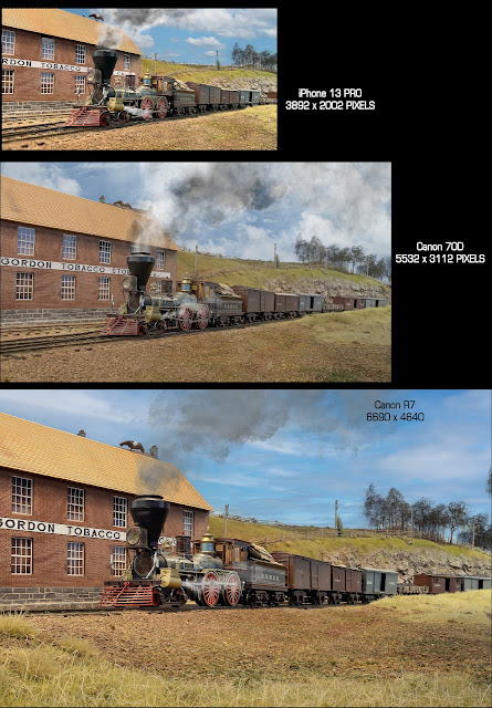
This next image is a comparison of similar images from the Canon R7, a Canon 70D and a iPhone 13 Pro. The relative sizes of the images shows their native resolution. The blogspot software shrinks images to save space on their servers, so you can't see the images at their true native resolution without using a file sharing service to save the full images. So I combined them in a single image to show the relative sizes.
The R7 is a 31 megapixel camera with 6690 by 4680 pixels. That means it can support a 22.3 inch print at 300 pixels per inch. That is more than enough to get a great two page spread in a magazine.
The R7 uses a APS (i.e. crop sensor). You might think that a 31 megapixel crop sensor would have problems with noise at high ISO. But that isn't usually an issue with model railroad still photography as we use a lot of light and can shoot at very low ISO. I used ISO of 100 in this test image. For action photography, the higher ISO needed to help stop motion can lead to noise. But both the Photoshop camera RAW and the Canon Digital Photo Pro software that comes with the R7 camera are pretty good at removing the noise.
I have found that cameras with APS crop sensors work better for model railroads than full frame sensors. I have had both. The crop sensor means the lens used on an APS camera have a telephoto effect. That forces you either move the camera back from the scene or use a wider focal length to get compositions that are the same as you would get in a full frame sensor. The bottom line is that you get more depth of field with a APS sensor in model railroad shots both for still and video shots. That is very helpful. Note this is opposite of what most other photographers want such as in portrait and bird photography, where they want shallow depth of field for the nice bokeh effect. I discussed that topic in more detail in an earlier post here .
Close Focus Distance
Beyond the amazing resolution, the camera with the kit lens has an astounding close focus distance. The grass in the foreground was nearly touching the camera lens. This obviates the need for a separate macro lens.
The camera is more compact than the 70D so you can get it in some tight places. But the iPhones cameras are better for shots like that.
Focus Stacking aka Focus Bracketing
The R7 offers automated focus stacking in camera. You enable this mode using a menu on the back screen. Once you enable focus bracketing, you then set the number of shots and focus increment you want to use. The focus increment is not defined precisely, so you might need to experiment. I have been using 10-14 shots and a narrow focus increment for my model railroad shots. There are some other settings for focus bracketing including a really neat one called "depth composite," which I explain below. You can find more info on this web page
Next compose your image. Then select a point in the foreground where you wish the focus to start. Once you hit the shutter, the camera will automatically take a shot, adjust the focus point, and shoot again until it reaches the number of shots you specified or the focus reaches infinity. The camera stores all the images on the card.
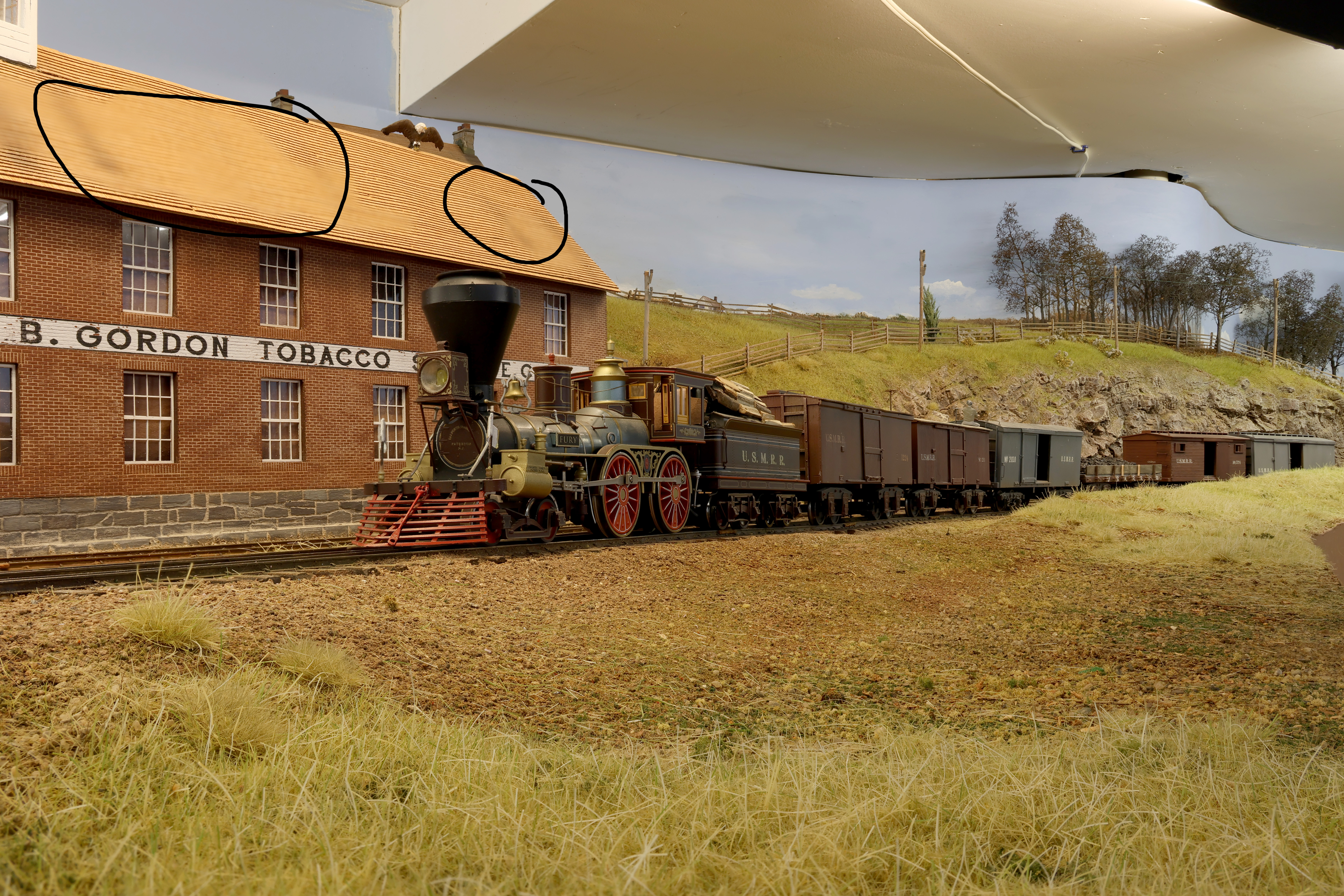
Example of stacked image using in-camera Depth Composite. Note the problem area in shingles as indicated by the circles.
If you selected to enable the Depth Composite setting on the camera menu, the camera will automatically make one stacked image from all the shots. That is amazing, but, I find it didn't give as good results as when I used Photoshop to blend stack. Look at the roof in the image at the left. The in-camera depth composite did not do a good job of blending the roof shingles.
Also, the camera saves the stacked image as a jpg file on the memory card. I prefer to shoot in RAW format not jpg. So in my work flow to date I have not been using the focus bracketing with depth composite enabled.
Instead I bring the stack of images into Photoshop. I use camera RAW to adjust the images. I synch all the adjustments, so the RAW images get the same adjustments. Then I do the align and stack in Photoshop. When photoshop is finished stacking, I flatten the image and do any special effects like sky replacement or adding smoke.
Focus Breathing
The kit lens also does not exhibit much focus breathing when doing the focus bracketing. Focus breathing (or lens breathing) is the phenomenon when the angle of view changes in your lens when you adjust the focus. When you focus from up close to infinity, you’ll see that the lens zooms out. It’s a small change, but a change nonetheless.
The change also happens when you adjust in the opposite direction. The lens will zoom in when you turn the focus ring from infinity to minimum focusing distance. If you go back and forth, it will zoom in and out. It’s as if the lens is breathing in and out, which is why it’s called focus breathing.
I could not detect any lens breathing artifacts when using this lens at a wide angle focal length. The artifacts would appear as out-of-focus fringes around objects that are closer to the camera. It is apparent in the iPhone image I posted above. Those fringes are very hard to correct as you must manually replace the fuzzy areas using editing software
Video
I put together a brief video showing how the automated focus bracketing works. It really is quite simple. It only takes a few experiments to get it dialed in to how you want it. I used 10 images to make my stack.
Bottom Line
The Canon R7 is an ideal camera for model railroad photography. It also rocks with a big telephoto for wildlife photography as it has very advanced autofocus capability, but that is a topic for a different blog


