A journal following the history, design, construction and operation of Bernard Kempinski's O Scale model railroad depicting the U. S. Military Railroad (USMRR) Aquia-Falmouth line in 1863, and other model railroad projects.
Using a laser-cut curve template to lay
the curve into Burnside's Wharf
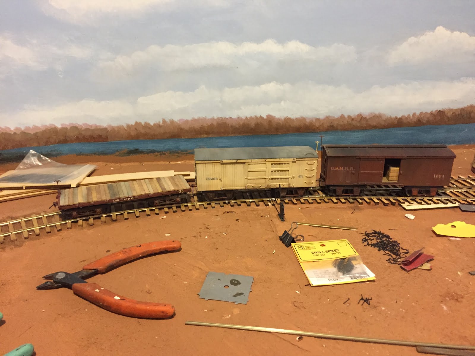
First cars to test the new curve to Burnside's Wharf
After a hectic week that included my daughter's wedding in Aspen, Colorado, 5 rounds of golf at different courses in Colorado, a very late night arrival home, a visit from a old friend, two golf lessons, a class in 3D computer aided machining, going to work and the usual chores, I was able to get some track laying done on the Aquia Line.
I managed to complete 3 more turnouts. That means I have only one turnout left and about 10 linear feet of track to lay. It's hard to believe after so many years of being under construction, all the track is nearly done.
Dr. Steve Clarson was in town for a conference. He, Alicia and I, had dinner and then toured the layouts. It's always fun to chat with Steve. Being a native Yorkshire man, he described the Aquia Line as, "brilliant." You got to love those British accents and dialects.
Prototype scene of traffic sharing road with train on Fries Ave in April 2000. Photo by Dave at EJ&E Archive.
After our unsuccessful attempt to get the "simple" grade crossing warning lights wired up using the materials I had on hand I decided to tackle the project anew. First step was to read the directions, again.
I am using a Logic Rail Grade Crossing Pro. It is a full function grade crossing circuit that can handle flashing crossing lights, motor control for gates, and a bell circuit. The user has to provide the lights, gates, motors and bells. In addition, if using LEDs, the user has to provide the appropriate resistors.
The wood screw in the center secures the
circuit to the benchwork
The instructions include a chart to tell you what resistance to use for the LEDs for several power supply voltages. I used a 12V power supply, so I needed 470 ohm resistors. Of course I didn't have any on hand. Luckily, we have a store in the area that sells some electronic components and is open on weekends. My go-to stores for that kind of stuff used to be Radio Shack as it was close to my house, but they went bankrupt. There is a good electronic supply shop in Alexandria, but they have regular business hours during the week and are closed on weekends, which makes it hard for me to get there during a normal work week.
Even though I was only using the crossing lights, there were still 14 different wires that had to be attached to the circuit and run to different spots on the layout. I made a wooden chassis with a terminal strip to try to help keep all the wires organized. I engraved letters on the wooden chassis for each connection. The large letters are easier to read when the circuit is mounted on the layout upside down. I also built harnesses for the wires that I ran to each signal and photocell. I used heat shrink tubing to make the harnesses. Unfortunately the magnet wires that came with the signals were fragile - two broke in the harnesses and two others shorted inside the tube. So I replaced all the magnet wires in the model signals with 32 gauge stranded wire.
The Grade Crossing Pro uses a series of 4 photocells to determine train occupancy and direction. You put the two photo cells on each side of the crossing and if you wire them correctly they will control the crossing in a realistic manner. The circuit includes potentiometers to adjust the photocell sensivity. I found that the adjustment would only work well when all four photocells were hooked up. Then it was simple to adjust for room light.
If I turn off the room lights the grade crossings will trigger if their power is on. So I have to make sure that switch is also off when quitting for the night.
It was a steamy rainy day as reinforcements arrived on the Aquia Line to help with various tasks.
Leonard White arrived first and he went to work in trying to wire up an automated grade flashing warning light system on the PoLA layout.
Joel Salmons and his son John were next up. They went to work laying rail and spiking track at Aquia Landing. This was John's first visit and he had a great time. He even asked to come to more sessions, including learning about operations.
Doug Gurin arrived next and also went on spiking brigade.
Leonard, with some help from me, did not have much luck getting the grade crossing signal system to work. I think we have a problem with the polarity of the LEDS on the grade crossing signals. I will have to take them off and double check that they are correct.
While we were working, Normal and Daylene Wolf stopped by to visit. They are on a weekend trip to visit DC to see friends and take in a Nat's baseball game. They hadn't seen the layout in several years and seemed to like it. I handed them a throttle and they had a chance to run a train around for a few minutes before they had to leave.
Right before dinner I glued down the ties for the new sidings at Burnside's wharf. After a great BBQ dinner where Joel and John joined Alicia and I, I went back to work on track laying and nearly finished one turnout before calling it a day.
Tonight I finished glueing down the last pieces of road bed for the Aquia Line. The roadbed is 1/8th inch poplar plywood glued to 1 inch of foam. I like this method of construction as it is fast, strong, light weight, and accepts spikes with no problem.
While I was laying the track I was thinking about how to switch this siding. I concluded that the original idea of having a turnout here is very handy, as it would prevent trains from having to back all the way across the wye to make pulls and spots. So I put the turnout back in the design and added a piece of roadbed for it. There is room in the siding for a 6-car train, which is also my design train length, plus 3 cars at the warehouse. The warehouse is recycled from McCook's Landing..
Here is the track plan with the siding shown at Burnside Wharf. I call it the set-out track, but it is like a visible staging track. Cars destined for Burnside Wharf will be spotted here.
The prototype photo below shows the area that this scene emulates, though it is on the wrong side of the landing in my layout due to the constraints of the room.
This is how the ridge behind the landing looks now. I
could expand the ridge to the left, but I like how the river
recedes into the distance in this view.
I could repaint the horizon on the backdrop to show the ridge line on the west since that would match the geography better. In that situation, the tracks would run along the right and then turn right into the river. But the prototype Aquia Landing is on a pointy peninsula surrounded by water on three sides. That is how I have the scene depicted my backdrop now. I like the way it came out, so for now I plan to leave it like it is. I just need to adjust some of the boats on the back drop as they are artifacts from before the expansion of Aquia landing.
I started the layout revisions for the former Burnside's Wharf area of the Aquia Line layout. I use some pink foam I had on hand and the warehouse from McCook's Landing to quickly mock-up how it might look. I immediately liked it. This test convinced me that the revised plan is superior to the former plan. The revised design gives me nearly the same level of operation potential and looks a lot better.
The other cool thing abut this plan is that it gives me an additional option if I decide to expand the Aquia Line. I can go with either an extension on the Falmouth side, or run a more complete rendition of Burnside's wharf as roughly shown as the track plan at the right. But that is in the future. For now it was time to initiate hostilities at Aquia Landing.
It was a simple task to cut the foam pieces to fit and glue them down with Alex Plus caulk. I also puttied in the gaps with fast and final spackle.
While the glue was drying on Aquia Landing, I shifted fire to the PoLA layout to continue to work on the Borax silos. I had to do some fit adjustments to the top plate of the silos. Then I proceeded to scratch build the unloading shed. I used a laser cut acrylic core, with some plastruct I-beams inside and Evergreen styrene corrugated siding on the exterior.
I had previously measured the height of the structure to insure that the stairs would fit in an even number of flights. My model is selectively compressed so it will only have four flights of stairs, while the prototype has six. There is a lot of cool detail on top of the loading shed. It will be fun to build that.
I've been thinking about the track plan for the Burnside's Wharf area and I decided to make some changes. The most immediate change is to eliminate the second wharf planned to represent Burnside's Wharf. I concluded that it was going to be too crammed in the spot I planned for it. I also want to get this part of the layout done before the ACWRRHS group arrives in September. I don't think I can get the second wharf done in time. In fact, I cut the number of tracks from two to one as I don't think I need the second track. (I can add it later once I start laying track.)
In terms of operation, I can still use the track in that area to represent trains that are destined to Burnside's Wharf. It would function like a visible staging track.
This design also makes the option of a continuous run more feasible by adding a removable track across the door to the dispatcher's office.
The second big change is at Falmouth. This would happen once I decide to remove PoLA and expand the Aquia Line. The more I live with the borax factory peninsula on PoLA, the more I realize I don't like it there. It's a little too tight for daily use. It also creates a choke point especially when I have visitors. So I took out the wye at Falmouth and reduced the bump out to only accommodate a tunable.
Last Friday we had a torrential rain that lasted most of the night. That caused some minor flooding in the basement. There was no damage to the layouts, furniture, or computers. But some boxes that I carelessly had placed on the floor got wet. I also had to pull stuff away from the walls to spray disinfectant. In the process I purged a lot of old stuff. The recovery is almost done, so I'll be back to building layouts soon.


