A journal following the history, design, construction and operation of Bernard Kempinski's O Scale model railroad depicting the U. S. Military Railroad (USMRR) Aquia-Falmouth line in 1863, and other model railroad projects.
©Bernard Kempinski All text and images, except as noted, on this blog are copyrighted by the author and may not be used without permission.
-----------------------------------------------------------------------------------------------------------------------------------------------------------------
Showing posts with label 3D Printing. Show all posts

October 30, 2022

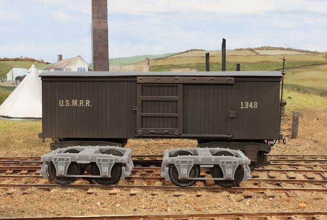
3D Printed Wooden Trucks


3D printed trucks

The expansion of the layout has resulted in a need for me to have more freight cars on the railroad. I haven't built any new cars for the layout for several years. I probably need to make some new flat cars, but I would also like to try some new styles of box cars. Regardless of what I build, I will need some new trucks. I decided to make them using my 3D printer.

I started by just drawing one quarter of the truck since it is symmetrical about the longitudinal and lateral axes. Once I had the quarter section fully fleshed out in the drawing, I used the mirror feature in Fusions 360 to complete the truck.
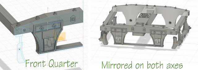


These trucks are designed to accept NWSL 8248-4,  O scale Wheelsets 33"/145,1/8"x1.730" shouldered axles. I have 5 sets of these on hand. Plus I have a few of my cast metal trucks that I plan to replace. I don't know if I can still get these wheelsets. If I cannot, I have a lot of Intermountain O scale wheel sets on hand. I would have to adjust the drawing to accept those wheelsets.  However, I prefer the NMSL wheelsets as they have thinner treads.


I had to design the truck in parts that must be assembled. The printed resin is too stiff to allow assembly by flexing the truck like you can do with N or HO scale plastic trucks. To ease assembly, I printed the bolster and one truck frame as single piece. Thus each truck has only 4 parts. Once the wheelsets are inserted in the holes on the truck frame, and the second side frame attached, the truck aligns itself. I apply some CAA and use a small clamp to hold the parts. While the glue is setting I insert the brake beams. On trucks without brakes, I glue those beams in place. But for trucks with brakes the beams are not glued. 


You can see how the brakes beams can pivot
I made the brake beams on pins so that they can rotate. That allows me the option to make the brakes work using my photo etched parts if desired.

I designed the bolster and brake beams to fit in slots or holes in the truck side frame. I learned that if you want to do this, you have to make the slots or holes larger than the corresponding pins by a fair amount. In this case I had to enlarge the 0.065 inch holes for the brake beams by about 25%. I had to reduce the bolster locating pin by about 50% to make them fit. I am not sure why, but holes and slots in materials print smaller than the design dimension by significant amounts. 


I was very pleasantly surprised to see how smoothly these trucks roll. They have a lot less friction than my earlier versions.  Printing 3D trucks will simplify my freight car construction as in the past it took me about 4 hours to build a set of trucks using my laser cut parts. These trucks also have more realistic detail, particularly in the journal cover area. 

This weekend I also worked on a wargame project with John Drye. I helped him build a map for a game he plans to run at Fall In 2022.  The maps depicts the area near Eindhoven and Son during the 1944 Operation Market Garden. The map is a 6' by 6' piece of felt that we painted and flocked. The graphics are designed especially for the new game called Breakthrough that Frank Chadwick is developing, and John is play testing. However, the map could be used for other game systems with a little modification. It was a fun project that came out better than we expected.

We used aerial photos as a guide but the terrain is stylized to suit the game system. I painted all of the fields, canals, and roads with spray can colors using soft masks. Then we embellished the edges of the fields with acrylic paints to show tree breaks. 

John is painting some details to help delineate the fields and roads.  


February 9, 2022

Cannon Fever


It's winter and we are cooped up. I have cannon fever. So, I drew a 1/48th scale 3- inch rifle, a common Union field artillery piece in Fusion 360 today.   I left a few details off the drawing. They will be added with the photo etched parts I have on hand.


Laser cut cannon with 3D printed limber

If you recall, I already have 1/48th scale cannon made with laser cut parts, cast metal barrels and photo etched detail parts. They look good, but require some assembly. If the 3D files work out, the 3d printed cannons will have much simpler assembly. 

Combined with the 3D printed limber I made a few months ago, I will be able to begin field artillery batteries as scenery items for the layout. If the test prints work out, the Aquia Line will be brimming with cannon soon.


To answer the question in the comment below, here is a table of cannons commonly used in the civil war.


Decal artwork

Last night I did some graphics work for Brian Kelly. He lives in our area and is modeling the C&O. He wanted a decal for a milk truck on his layout. But, all he had was a rough photo of the company's logo from a cloth patch. He asked me to redraw it so he could make a decal. I am including it here in case anyone else might need it.  You can re-size it as needed when you print the decal.


January 27, 2021

Is 3D Printing Scratch Building?

This question has come up on some modeling forums in which I participate.  The immediate follow up question is, "who cares?" Well, some people do, especially when it comes to contests for model builders.  The NMRA is not alone in hosting modeling contests. In fact my impression is that plastic scale model builders and figure painters are even more focused on contests and awards than the NMRA.

A similar question arose when digital photography became available. At first the film advocates argued against digital photography in contests. Now, 15 years later, film is dead and no one thinks twice about digital photography. I suspect the same will happen in model building.

The NMRA has addressed the subject of 3D printing in its requirements for Achievement Program judging.  From the NMRA website

The term "scratchbuilt" carries the implication that the builder alone has accomplished all of the necessary layout and fabrication which establish the final dimensions, appearance, and operating qualities of the scale model.  This definition does not prevent the use of any tools or jigs as long as the builder alone has done the work necessary for the tool to make the part.  This would include drawings or computer files to control CNC, automatic lathes, laser cutting machines, 3-D printers, and other tools.  If a third party changes the builder's inputs, then the parts are not considered to be scratch built. 

Meanwhile, other modeling contests have taken a different approach. For example, The rules for the  Bandai Hobby Open, a modeling contest for models made using parts from Bandai kits, says, "a part which is made by 3D printer or 3rd party resin will be not judged." Now this may be because they are trying to promote the use of their own kits, though they will allow, "scratch built parts." So clearly they lump 3D printing in  the non-scratch built category.

If you frequent modeling forums you will see a split opinion on whether 3D printed parts can considered be scratch built. For example, one fellow made an interesting point that it is much easier to make a perfectly symmetrical part when 3D drafting and printing, so called additive machining, than by traditional subtractive machining. OK, that might be true. So what. Use the right tool for the job I say.

I view 3D printers, laser cutters, CNC milling machines, computer controlled paper cutters simply as additional tools in the model building arsenal. If you start with raw materials, you do the design work,  and it becomes a part, then it's scratch built. If you buy a 3D printed part, or you download a stl file to print on a 3D printer, then that is not scratch building any more than buying a commercial injection molded or cast part would be.  That pretty much is in line with the NMRA guidelines.  

I suppose one gray area might involve a person that designs a part, but has a commercial house, such as Shapeways, do the printing. That might not meet the NMRA guidelines.  I know from my own experience that printing the parts on your own machine can take a fair amount of experience and skill. 

3D scanner in action
I am not sure how 3D scanners fit in this category, as those seem to be more like a copying process. But, I suspect there is a lot of art and skill involved in making a useful 3D scan that can become a 3D printed part, so I will remain open minded on that. I read that the new iPhones can do 3D scans, so the technology is becoming more and more available.

Kit bashing is a gray area that lies between scratch building and not.   The NMRA allocates a variable number of points for scratch built content in contest or judged models, so they recognize there is a continuum is this area. Furthermore, the NMRA did adapt their AP requirements to allow super-detailing, especially diesel models, as an acceptable way for a model to gain points in their scoring system.  

In conclusion, this is not an question that I get too worked up about. I do find it an interesting subject and thought it worth some discussion.  I am not a big advocate of model contests in general due to the great amount of subjectivity it involves. I think the NMRA merit system is actually a pretty  good approach. 


December 5, 2020

Coffee Wagons and On-Demand Figures

 I recently discovered this website that prints miniature figures on demand. They have an extensive set of ACW era figures.  They offer several scales. 

https://www.speira.net/product-category/american-civil-war/

I ordered several of the Speria figures including some limbers, wagons, and the coffee wagon set.  I never heard of the ACW coffee wagon before, so I looked it up. 

They were built by the U.S. Christian Commission to improve morale. From other research I know the the U.S.C.C. had several stations on the Aquia Line. The timeline might not be quite right as the coffee wagons were patented in March of 1863, which is the month I model.  But, I love coffee, so it's a must have.

The coffee wagon reminds me of how I first became a coffee drinker. Prior to being in the Army I never drank coffee. But, one cold and misty night I was at a bridge site on the Main River near Bamberg, Germany. We had just finished building a bridge and a steady flow of military vehicles were crossing the river over our bridge.  It was about 3AM and the mess sergeant showed up with a Cambro container full of hot, strong coffee. He made the coffee by dumping the grinds in the bottom of boiling water in the Cambro container. Then they would put the Cambro on the back of a jeep to deliver to the bridge site. Driving along in the back of a jeep, the water and grinds were agitated making strong coffee, especially near the bottom of the jug where it was like mud.  So, being cold and tired, I tried a cup of black coffee. Wow, it was great. So, I started drinking it more and more. Later, when I stayed at a German or Austrian gasthaus, or Italian hotels on ski trips, etc, I would drink their coffee, which was always strong. That is why to this day I love strong coffee.  But I do like a like creamer and a tiny amount of sweetness (like 1/8 teaspoon of sugar). 

I think the coffee wagon and figures will make a nice mini-scene on the layout. 

Brian Fletcher from the ACWRRHS also writes about his connection with the Speria Miniatures. He is involved with the Waterloo Uncovered diorama project group.  Waterloo Uncovered is a charity that supports wounded ex-soldiers come to terms with their conditions through the medium of archaeology.  Every year, the charity conducts a dig at Waterloo and, as well as uncovering new perspectives on the battle, the many soldiers who attend enjoy being part of the project.  In the first few years, the focus was at Hougoumont but recently work has expanded to other parts of the battlefield. 

Speira have been generous enough to supply them with free figures for their non-profit organization to complete the Waterloo battlefield 1:1 in 1/72nd, scale.  He has their figures in 1/72nd. 28mm. and 1/48th.   He says all are excellent and reasonably priced.  Most extensive line is ACW.  They are a small company but highly recommended.  Any figure painters who want to join the Waterloo Uncovered project are welcome.  They have need for another 40,000 Napoleonic figures.  There will be over 100,000 all told.  Over 60 painters worldwide and growing. Diorama will be displayed at the National War Museum in England June 2021 if Covid permits. Some figures are free to a good home.  

December 4, 2020

The Many Pitfalls of 3D Printing

If this is starting to seem like a computer blog, please bear with me. Three-D printing is really applied computer science, so you need delve into such arcane matters. Those of you that follow my blog know that I hate when computers take over my model railroad. That is one of the reasons I model the 1860s. I do not enjoy  wiring and dread the thought of maintaining a large fleet of locomotives with DCC technology. But, I can't deny that technology has made modeling a railroad set in this period possible as there is almost no commercial support. I have embraced computer aided drafting of track plans, laser cutting, DCC, battery power, microprocessors, LED lights, and now 3D printing to accomplish my goals.

So with that preface, let's look at another pitfall awaiting the modeler as he explores the dark, sticky morass of 3D printing. To date most of my 3D printing objects have looked incredibly detailed with nearly invisible layer artifacts. That is why I was puzzled by the facets visible in the first prints of the boiler I made. They required a significant amount of sanding to smooth.

Visible facets on boiler sides 

I decided to see how hard it was to prepare the boiler for painting. I primed it with Rustoleum Filler Primer. I sanded it as described in my previous post.  I used 220-400-600 grits to get a nice smooth surface. Then I sprayed with a coat of Vallejo Black Primer which I had on hand. I don't like this primer as it doesn't seem to self level well, and you can not wet sand it. I don't plan to use it again. 

Paint test on an early version of the model
Next, I sprayed a coat of Future acrylic floor polish to get a nice glossy surface. When that dried, I sprayed  the final coat of Vallejo Natural Steel.  This is not the paint I plan to use for the final model but I had it on hand. The results were good in the areas that I was able to effectively sand. But against the boiler straps (which remain unpainted in the photo), and along the firebox, I could see artifacts of the print process. 

This got me wondering if there was something I was doing wrong in the 3D print work flow that created the facets. After some google searches and checking with the Fusion360 help forum I had the answer.

Non-computer jocks can skip the next two paragraphs. In my Fusion360 workflow, I had been using the "Export" command to save the artwork as a .stl file for 3D printing. For some unknown reason, Fusion360 uses a server to do that conversion. So, you have to send the file over the internet and it sends back the .stl file after about 3 or 4 minutes. This option does not allow any customization of the conversion settings. It is also slow as the file has to be sent over the internet. In this case the resulting .stl file was 75MB.

But, there is a better way. If you right click on the object in the Fusion360 component browser a pop up menu with several options opens up. Buried in that list is the option to "Save as stl." If you select this, another pop-up window opens with options to change the settings of the stl conversion, including the option for a "highest" quality file. The default was "medium" quality. Now that was obvious! (sarcasm alert)

For the small objects I printed so far, medium quality was good enough. But on the large boiler the medium setting was not good enough. So I saved the file as a high quality stl. The resulting file was 550MB, nearly 10 times larger. But it saved it nearly instantly. Win-Win.

So I set about printing the boiler again. After 9.5 hours on the printer I ended up with a much nicer product.  There are no visible printer artifacts as you can see in the photo below.

New boiler print on the highest quality settings
 The frame in these photos is a temporary one made with laser cut MDF. I have ordered a 3D printed part from Shapeways using SLA "Accura Xtreme." which according to their website is "Accura Xtreme is a gray and rigid acrylate-based plastic. It is 3D printed using a large format stereolithography (SLA) printer capable of producing small to large parts with high resolution and detail as well as smooth surfaces with limited layer lines. This material is well suited for challenging functional assemblies with a smooth, injection molded-like surface finish." Seems like a good option for the frame.  If that is not good strong enough or is unsightly, I will pursue other options. Once I have the frame, I will set up the motor and gear box and  try to get it to at least turn the front drive wheel.

In the meantime, I have other tasks to do like make the cow catcher, the cab, many sundry other parts,  and prepare the artwork for laser cutting the rods and fine details. Those will be sent to a commercial laser cutter than can handle cutting metal. 


November 24, 2020

Teaching an old dog new tricks


Many thanks to all of you that expressed sympathy on the passing of my mom.  It's been a rough stretch, but getting back into my modeling projects has been a good tonic. So I'm back in the shop, well actually mostly on the computer, as I restart work on the locomotive.  The locomotive build project and techniques I plan to use on it are evolving as I work on it.

First, last month I purchased a Anycubic Photon 3D resin printer on sale. The price was less than $200. I also got their wash and cure machine, a few bottles of resin, some rubber gloves and alcohol. So I started dabbling in some 3D printing. 

Since I am mostly interested in printing items that I can use on my railroad, I'm pretty much stuck learning how to do 3D drafting as very few fine scale models of civil war era stuff are available. I had a little prior experience with 3D drafting, but I needed to learn a lot more to be proficient. The best way to learn is by doing, so I dove in. 

First useful parts from the 3D printer
The Photon machine is capable of very high quality prints when everything works. So far my success rate has been about 50%. But, I have made some useful parts including a smoke stack for the loco, some civilian figures for the layout that I downloaded from various sites, and a test print of the cylinders for the loco. Learning how to do 3D printing is a skill, or perhaps art, all on to itself.  There are hundreds of YouTube tutorials and websites with help. So I won't cover that here. I will say that 3D printing does change how you look at modeling projects in much the same way that the laser cutter did when I got my first laser about 14 years ago.

As I discussed a few posts ago, I was planning on laser cutting the frame side rails along with some other parts from metal using a outside service. I still plan to do that for the drive rods and some of the valve gear. But, I think I will have the frame and the cylinders 3D printed in metal from Shapeways. Various folks have reported good success in printing locomotive parts in brass. Unfortunately, my frame is too large for their brass 3D printing process. I could cut the frame in parts and solder them together, but I think I will try make the frame in some other 3D printed metal. Shapeways makes their parts in brass using a lost wax process. They also have other techniques for printing steel (actually a steel-bronze matrix) and many other materials. The metal prints tend to be much more expensive than plastic and it looks like their surface texture is not as good, so I need to tread carefully here.

One of the reasons for opting for 3D printing, is I decided to draw the locomotive, or at least most of the critical dimensioned parts in Fusion360.  Since I was creating the 3D file, I thought it might be fun to try printing several of the parts.

The design of the rear of the boiler, the firebox and the back head are tricky and warranted looking at their geometry in 3D. The fact that the boiler is wider than the frame helps complicate the design. Also, the compensating sub-chassis also requires some tricky cutting of parts to make room for it.  So the 3D plan is helping me check all the fits and dimensions. For example, by drawing it in 3D, I detected a problem with my 2D drawing in the area of the back head and cab floor. I still haven't sorted it out yet, but the 3D exercise has proven useful. 

I am also enjoying learning the program, although some things are very confusing to me. I still haven't fully sorted how to align objects. Steps that would take me 10 seconds in Illustrator took me hours to do in Fusion360. One of the factors that made my life more difficult is that I imported DXF files from my 2D drawing to use in the 3D drawing. But, when it comes time to make changes to parts derived from the DXF files, things get tricky. At this point in my Fusion360 skill level, I find it easer to start with a fresh sketch in Fusion360.  Anyway, I'll keep plugging on. 


November 2, 2020

Leaving the Stone Age

Yes, even a cave man like me needs to evolve. For many years I've had learning how to do 3D drafting for 3D printing  on my do list. This past week I finally started to make a more serious attempt to learn 3D drawing, first with Tinkercad and now with Fusion360. While I am still an absolute neophyte in the applications, I was able to make a few decent drawings. 

As I mentioned in my last post, I drew a smoke stack for my locomotive project using Tinkercad. Unfortunately, that drawing did not have enough polygons to make a decent 3D print despite my setting it to maximum steps. 

So, I decided to try drawing the same part in Fusion360. It took me a few hours, but I got a decent drawing that Shapeways says will print.   I have an associate that has a high resolution resin printer that will try to print it for me.

 Emboldened with my newly learned skills, feeble as they are, I tried doing a test drawing of the frame of the locomotive. 

I exported the side frames as a DXF from my drawing in Adobe Illustrator. Then I imported that into Fusion360, copied and offset it the appropriate amount,  and extruded some cross members.

The resulting image looks like this.


Then I uploaded the frame part to Shapeways to get an estimate of the cost to print in metal. I was surprised to learn that the frame would cost about $50 including shipping if printed in steel. I thought the price would be much higher. So now I think I will proceed with finishing the drawing in 3D including adding the cylinder and smoke box saddles, and perhaps the cylinders and hangers. Then trying printing the frame in steel or aluminum. The steel printing process involves a furnace sintering step that results in shrinking. So steel might not be a good choice for this part. The aluminum process uses direct laser melting of aluminum powder, so it is more accurate and doesn't shrink. But it is three times as expensive. 

One advantage of 3D printing is I can add some additional detail to the springs to better capture how they look on the actual locomotive. Also, the frame will be assembled when it is printed. I do not know the tolerances that the 3D printed metal will allow, but most of the dimensions are not critical. I will make the holes undersized and uses reamers to get precise diameters.

I will proceed on the drive rods and valve gear with laser cut nickel-silver or maybe stainless steel.

Meanwhile, the brass tubes and some sheet nickel-silver I ordered arrived. The boiler will be made from a section of 1.125 inch brass. The side walls are 0.064 inches so the inner diameter is just under one inch. The motor will fit nicely inside. The thick walled brass will also add some heft to the loco. 


October 31, 2020

Changing My Approach


Last week I made some drive rods for the locomotive project and installed them. I cut them on the laser from two layers of  0.025 inch laser board. Then I glued the layers together.  They fit very nicely on the crank pins that come with the Slaters Wheels.  This short video shows the trucks rolling on the track.

This rolling test rig demonstrates the effectiveness of the compensating beams. I will need to add some spacers or make some new bushings for the space between the wheels and the compensating beams to limit some of the sideways play the axles.

As I was working on this project, I've been searching the web for materials and parts. I came across several companies that offer laser cutting of metal. I found a shop in Utah that will do small jobs. They have  4KW and 8KW lasers that can cut up to 1 inch thick steel. That is 1000 to 2000 times more powerful than my laser cutter.

They have some neat software on their website that takes .DXF files and converts them to 3D depending on the material you select. Then their software examines your files for problems and if all is OK, you get an estimated cost (see figure below.) Since this looks so easy to use, I decided to use their service to laser cut my frame parts from 0.075 inch thick stainless steel. I will also submit drawings for the valve gear and some other parts to laser cut in 0.020 inch nickel-silver. The drive rods will be included in that file as well as the parts for the compensating sub-chassis. Since the nickel-silver material is only 0.02 inches, I will double the drive rods and solder them. Nickel-silver solders very nicely. The nice thing about laser cutting metal is that for small jobs the cost is much lower than photo etching. 

The draw back to this approach is that I now need to draw all the parts of the model before I submit them. My earlier  approach of designing as I go will not work. Also, I decided to move ahead with engine Leach. I am using the Talisman drawing to inform the Leach drawings. But Leach was a bigger and heavier locomotive. 

So, now I am in the process of drawing the model in side and front elevations. Those two drawings should be enough for me to create drawings for laser cut parts. I will do test cuts at home with 1/16th MDF and resin-impregnated laser board to make sure the fit and function are OK.

I have spent a good part of the week doing these drawings and ordering materials. It's kind of a iterative process as you must design your parts for size materials that you need. So depending on what is available, you adjust the drawing. For example, brass tubes for the boiler are limited in available diameters. I went with a 1.125 inch diameter boiler on this loco as Leach had a chunkier boiler than other engines. At 1:45 scale, 1.125 scales up to about 50.6 inches. White says in his book on American locomotives that most boilers were under 48 inches in this era. But the photos of Leach show a boiler slightly bigger at somewhere between 50 and 52 inches. I consulted with John Ott on this issue as a sanity check and he agreed. 

The image below shows the work-in-progress of the drawing as of tonight. I have about half the parts I need to draw for laser cutting done. The blue parts at the bottom are the frame parts. The silver parts are some of the valve gear. This drawing also shows how the motor and gearbox fit in the loco. I may not have room for much of a flywheel as it would extending the cab interior. 
Abode Illustrator drawing to plan out the laser cut part.


This image at the left shows one of my frame parts loaded onto Oshcut's website as I tested it for problems. This will be  0.075" stainless steel. Note how I was able to include the spring details on  the chassis. Those would have been very difficult to machine without CNC milling.


Screen capture of a .STL file for 3D printing
 of the smoke stack.

Since I was doing computer drawing, I decided to take a crack at drawing a smokestack for possible 3D printing.  See the image at the right.  I have never drawn a 3D part for printing before, so this is a first for me. I used Tinkercad to draw this smoke stack. I have Fusion360, but I am not familiar with it enough to try this. Tinkercad is very easy to use, though not as powerful as Fusion360 and some of the other 3D software out there. I exported the image as a .STL file and sent it to a friend that is doing some other 3D printing for me for Alkem Scale Models. His resin printer does a better job than Shapeways. I am curious to see how it comes out. 

Also this week I briefly considered getting a milling machine so I could cut the parts as needed from stock materials. But I decided the laser cut parts are probably superior for this project. I may get a small 3D printer though as they are much less expensive these days and the resin printers do a great job. 

So all in all it was a busy week with a lot of computer time both researching information and drawing.