A journal following the history, design, construction and operation of Bernard Kempinski's O Scale model railroad depicting the U. S. Military Railroad (USMRR) Aquia-Falmouth line in 1863, and other model railroad projects.
©Bernard Kempinski All text and images, except as noted, on this blog are copyrighted by the author and may not be used without permission.
-----------------------------------------------------------------------------------------------------------------------------------------------------------------
Showing posts with label Bridges. Show all posts

September 8, 2022

Back to Spiking Time


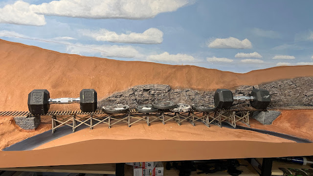
Forty two and a half pounds of weight to hold the trestle while the glue dries


I finished installing and carving rock faces by the bridge site and balloon camp. 

Black base coat on rocks

Next I painted the rocks. I use Durham's Water Putty for my rock carving material. It has a yellow color. So I add brown acrylic paint to the putty mix. But once the putty is dry I paint the whole rock face black. Then I dry brush white from above to create the zenith highlights. At this point the rocks look like a black and white image.


Color Palette

Next, I take dark brown, burnt sienna, medium gray, white, and tan acrylic paint. I brush the rocks lightly with these colors on a wet brush to catch the high points. The brush is not so wet as to run and puddle paint in the crevices. It's a like a dry brush technique but with a loaded wet brush. 

I did a quick job of painting the creek bed. This will be covered with layers of other scenic material so the paint wasn't critical, but it will look like a acceptable before I get to that.

Once the rocks and creek were painted, I inserted the bridge into position. I adjusted the fit slightly by cleaning away any stray bits of putty. Then I glued it with carpenter's yellow glue. I put 42.5 pounds of weight to hold it it position.

Zenithal highlights with white paint


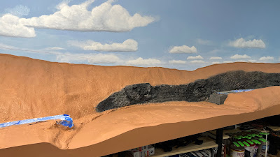
I didn't finish the terrain over the tunnel. That will have to wait until the rails are spike down. 


September 5, 2022

Snow in September?


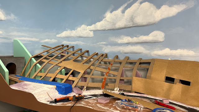
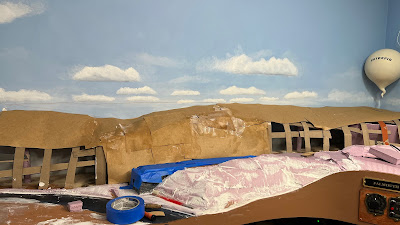
I spent the past two days working on the terrain of the ridge between Falmouth and Stares Tunnel. I decided I needed to get this messy work done before installing the bridge and laying the track. 


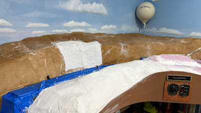
I used the cardboard web to build up the overall shape. Then I applied a layer of thick paper, sometimes called rosin paper,  used to protect floors. The first layer of rosin paper was dry as I used hot glue to stick it to the cardboard ribs. Then I applied another layer of rosin paper that I cut into smaller sections, soaked in water and secured with white glue.   Once that dried, the terrain structure was reasonably solid.


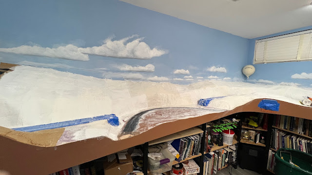
Next I covered the whole surface with a two layers of plaster impregnated gauze.  Now I need to let this cure before I can paint it with the base scenery color.

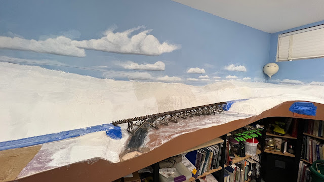
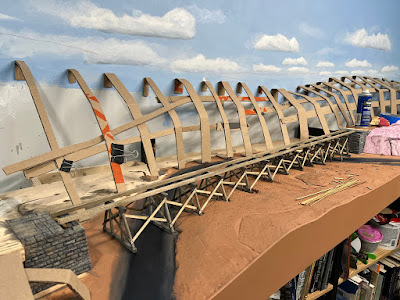
The bridge is a sturdy enough that I can insert it to test fit and then remove for scenery work.


September 2, 2022

Decisions, Decisions?

I installed the ties leading from the tunnel to the bridge and on the far side of the bridge. The overhead view shows how the track pops out of the tunnel, crosses the trestle and then begins the curve by the balloon camp to Falmouth.

I had to remove a section of O scale flex track. The nail nippers were incapable of making the cut and I accidentally pulled some to the rail out of the cast in spikes. Arrg. I was able to fix the damaged track with CAA. 

Next I started extending the terrain formers from the bridge site toward the tunnel. As I laid it out, I began to think that I have the tunnel recessed too far into the hill. The two pictures below show the original design with the deep cut, and a revised design where the tunnel portal is moved forward creating a more shallow cut. The more I think about it the shallow cut looks better.  Instead of moving the tunnel forward, I could cut the slope of the hill and stick with the original portal location with a shallow cut but further back. But the idea is this is a steep ridge that caused the creek to make a sharp turn, so the steep hill works better for that.  I have a few days to decide as I have to spike the rail before I finish the formers.

I used my Festool Rotex 90 with 60 grit coarse paper to reshape the hill under the trestle to remove the deep holes for some of the sills. The dust extractor really cuts down on the mess. It is a great way to shape foam terrain. 


ANOTHER EXPANSION?

As I was gluing down the ties I had mixed feelings. Is this truly the last ties I will be gluing on the Aquia Line? Probably, but there is a slim chance I might do another expansion. What that would look like is show in the track plan below, which I labeled version 40 thought it's probably more like version 200. 

The big draw back is the very reduced crew lounge. The location of Burnside's Wharf is also an issue. Option A has it in the office space accessed by a section of hidden track, which can be access from below if necessary.  Option B has it on the wall above my work bench and accessed by a removable section. That is an interesting use of that space, but I would lose the overhead clearance I need for my 3D printer.  So I would probably move the 3D printer work station under the peninsula and place it on castors so I can roll it out when I need it. 

What does the decision matrix say? Burnside Plan A is tied with the current Plan in  sum of ratings. Burnside Plan B is a close second but loses points for the removable section that can result in a duck under during operations, while Burnside Plan A has a bit more hidden track. The current plan wins on Sum of Ratings weighted by Priority due to the crew lounge priority but only by on point.

Locating Burnside Wharf in the office is both good and bad. Crews switching Burnside wharf will interfere with the dispatcher. But the longer run to Burnside Wharf captures the prototype better.

Aquia Yard limits would extend all the way around the new peninsula to the switch to Burnside Wharf. That is where the telegraph station is now, so that works.


Decision Matrix for the expanded plan versus current plan

The numbers show what I expected, the expansion trades the crew lounge space for more main line running but it is very close.

 Now to convince Alicia (and myself) that this is good idea.


September 1, 2022

Trestle is Ready for Track


Bridge will be ready for rail once the glue dries


 Jack Thompson came by today to help work on the layout.  He drove spikes while I assembled the bridge. He got about 3 feet done before he had to leave.

The first step for me was to paint the creek bottom using Paynes Gray and the base scenery color.    I also painted the abutments in the same style as the other bridges on the layout and glued them in place. 

 I add the diagonal braces to the bents. That required the tedious work of adding 16 NBWs to each bent where the diagonal touched the uprights - 208 total. 

As I prepared each bent, I glued it to the stringers but left the bottom sill unglued. I used a weight to ensure the glue joint had a good bond. 

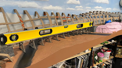
 Once all the bents were attached to the stringers, I used my 48 inch level to make sure the stringers were straight. I was amazed to find that they were. So I started adding the diagonal braces that ties the bents to each other. Then I added another 72 NBWs.  The NBWs are tedious but they do provide some nice detail to the wood structure. 

The last task for today was to glue glue down the ties on the bridge.  Once they are dry, I should be ready to start spiking the rail across the bridge.


August 28, 2022

Getting Bent


We returned home from a great visit to see my granddaughter and her parents in Alabama. I had several other projects to take care of before getting back to work on the layout. Today I was able to build all the trestle bents for the low trestle over Mueller's Creek.

I started the bridge by making the abutments from pink styrofoam. I used my miter saw to cut the core pieces and a razor saw to cut away the ledges for the bridge stringers. The abutments will be covered with stone plastic sheet by Ratio models in the UK. I used that plastic stone on my other abutments and it looks great. 

Next I added  the stringers and trestle bents. In my first attempt I used 3/8 inch square stringers and ¼ inch trestle parts. After making 5 of those bents I decided the trestle looked too beefy. So I swapped out the 3/8th stringers with ¼ inch. I replaced the ¼ inch posts with 3/16th inch dowels. I think  this spindly look is more appropriate for ACW era bridges.  The 3/8th stringers were pine while the ¼ inch ones are basswood. The grain on the basswood is much more in scale than the pine, especially after I embellished the grain with coarse sandpaper and razor saw. 

This was tedious work.

I had to make each bent individually as the ground below the trestle is not flat. In addition, the bridge itself is on a grade. So each trestle bent had to be made to fit the intended location.  I did not worry too much about variation between the bents as the prototype bridges had a  very ad-hoc look.   

I pre-stained all the pieces before assembly. I made a crude jig to glue the vertical posts both joists. But each diagonal I measured and cut by hand.


The plastic sheet stock for the abutments is visible behind the bridge,


February 24, 2021

Revised Artist Concept for Mueller's Creek Bridge


This is my revised concept for the new section. The scene will entail one long trestle that spans the bend in the creek with a small raised section of land and some trees in the center of the bend.   

 I am calling the area Mueller's Creek in honor of a friend from the ACWRRHS who passed away two years ago and his wife who also passed away after an accident on the stairs at her church.  Al and his wife were great supporters of the ACWRRHS. Al was an accomplished modeler who did wonders in rebuilding  HO Mantua locomotives into fine running models. 

Note to self - yes you have to actually build the layout. You can't just draw it in photoshop. 


February 22, 2021

All Mocked Up and No Place to Go

 Thanks to everyone that commented on the previous post. Here are some more of my thoughts on the scene. I hope to install the water level plywood soon, so I need to sort out the design.


I cut some cardboard to mock up the fascia. The exercise proved illuminating.

First, I determined that I should add some more lateral distance between the fascia and the track, i.e. make the layout benchwork wider. This is mostly so that when I take photos or shoot video, I have a little more terrain to work into the scene. But it also improves the scenery to the track ratio, making the layout more realistic and visually pleasing.  This goes against some currently fashionable layout philosophy to have minimal bench width so one can maximize run. But in this case, I have plenty of room to grow the width of the scenery since I already have maxed out my linear run. The extra width will be infringing on a generously sized crew lounge where a few less inches of space is not critical. 

Second, the mock up shows that the vertical bump in the fascia isn't really that effective as a scene divider. Plus, I surveyed the rest of my layout and determined than I have eight other locations where I have terrain higher that the track between the fascia and the track. But, I have only four places where the terrain at the  fascia is lower than the track.  So I need more below grade terrain. Below grade areas also make better photo opportunities. 

The desire to break up the scene to make the run feel longer is not as imperative here as elsewhere because the run from Stoneman's Station to Falmouth is the longest I have on the layout -  about about 50 feet with 16 feet in the Stares Tunnel. It takes about 3 minutes of run time at track speed.  It's true that in model railroads, the length of run can never be long enough, but this is getting close, or at least as close as I can get in this basement without going to a double deck layout design.

The only image of Accokeek bridge I have.
Third, one of the common features of civil war era railroad construction is the use of trestles over undulating land versus excavation of cuts and fill. Before bulldozers and dump trucks, cuts and fills were more expensive, at least in the short term, than wooden trestles.  And ante-bellum railroad builders aimed for fast and cheap. The USMRR followed this philosophy even more on lines they built.

In the case of the Aquia Line, the USMRR built over an existing roadbed, so the grading was largely complete. But, there was a long low trestle over Accokeek Creek. Haupt says it was about 150 feet long and 30 feet high. I only have one image of this bridge and it is a quick artist's sketch, not a good photo.  Not much help there. I don't have room for a scale 30 feet  of height, which would be 7 inches, so I need to aim for a lower style bridge. 

Bridge Number 2 City Point and Army Line
Fortunately, the USMRR built many bridges like that and we have photos of several of them. The USMRR City Point and Army line has several examples of low trestle bridges like this.  Bridge number 2 was a modest one, while the bridge over Hatcher's Run was much longer.  The USMRR built extensive trestle work at Aquia Landing to connect Burnside's Wharf to the mine line. So there is ample prototype precedent. 


Fourth, I think a long low trestle would look really cool.   Gary Hoover has an impressive low trestle on his new N&W layout. Paul Dolkos has one with a swing bridge on his new layout.


In conclusion, a long low trestle is a typical USMRR construction feature, it would amplify the narrative of mid-century railroad construction and  it would look cool.  I will use some foreground trees to help break up the scene, but the trestle will be uninterrupted by a cut and fill. 


February 21, 2021

One Versus Two Bridges?

I installed the benchwork and roadbed for the expansion as the track departs Stares Tunnel. The curves are 36 inch radius minimum, though the curve just as the track departs the tunnel is mostly eased to a much greater radius. The flow is nice and smooth. Turns out the grade in the tunnel is greater than in this visible section, so there isn't that much more to worry about. 
Now I need to decide if I want one long trestle or two smaller bridges separated by a short section of cut through a hill. 

I did two concept sketches using Photoshop to show how both might look. The comparison photos are below. Which do you like better- one long trestle, or two short bridges with a short cut in between?How about both, that is have the long trestle, but have some trees in the marsh in the middle foreground. The trees would help break up the scene, but still allow the long vista.


The compromise solution - long trestle with a slight rise in the middle with some trees.


January 30, 2013

Baby needs new shoes

As I mentioned a few days ago, the bridge needed some type of shoe where the lower chords touch the abutments. This required that I remove some of the stone on the abutment to allow room for the new bridge shoes.

The abutments are two layers of aspen wood, so it was fairly easy to cut away one course of the stone from the first layer. I sanded the cuts smooth and then added a thin layer of Milliput to simulate the cut stone face. Once that cured overnight, I repainted the abutments and the surgery is barely noticeable.

I made bridge shoes from a piece of 0.25 by .375 inch basswood stock using prototype photos as a guide. I glued the shoes on the chords and test fit the bridge. One abutment needed a minor tweak and it was done.

As I looked at the bridge installed, I decided I did not like the contrast between the dark burned laser-cut edges versus the uncut edges of each member. So I used my airbrush to spray a thin coat of Vallejo Light Brown over the laser cut edges to lighten them. I thinned the paint about 50 percent and sprayed in light passes trying not to obscure the detail and avoid overspray on other parts. In the end, the effect worked and I think the bridge looks much better.

Now it's ready to be glued in place and track spiked up to it.


January 28, 2013

Truss Bridge Complete

I finished the truss bridge by fixing the reversed braces and adding the abutments. The braces now point in the correct direction.

The bridge was longer than we planned, so I had to do another iteration of shaving the left abutment to make room. I made the abutments with a double layer of 1/4 inch aspen wood. I laser cut the stone patterns. Then I added a layer of Milliput putty to the surface to simulate the rough stone typical of the era.

There is not a lot of clearance between the bottom of the bridge and the water, so I did not add a any type of bridge shoe.  However, there probably should be something. Adding a bridge shoe will require a slight modification to the abutment, but it is not impossible.

The bridge can currently be removed with the track since it is spiked on it. Once it is installed, we have to glue it in and attach the rail with joiners to keep it secure.

Next on the critical path is the turntable. I was planning on using my current turntable and popping in in place here. But now I think I will build a new one just for this layout.

One other task I wrapped up this evening was painting some figures. I started painting some of these Sash and Saber figures a few years ago, but never finished them. So tonight, I took two of the Trident miniatures and painted them along with finishing the other batch of Sash and Sabers. I painted these as African Americans with a Caucasian officer. These soldiers will represent part of the USCT infantry assigned to guard the depot. This was a typical mission for the newly raised USCT units at this time period. The Trident figures are very nicely sculpted. I would rank them as the best of the ACW 40mm figures I have tried.


December 1, 2012

A cupcake too far

Gerry Fitzgerald and Joel Salmons stopped by for today's cupcake, I mean work,  session. Brian and Michele also stopped by after the Scottish Christmas Walk to have a cupcake and check the  progress. Last, but not least,  Doug Gurin, the now famous Model Railway Show podcast personality, stopped by for a status check, plus a cupcake and slice of Gerry's infamous chocolate cake from Charlottesville (too bad most of us are on diets).

Gerry and Joel score and snap the pink foam
Everyone was satisfied with the LED lighting, drapes and bunting. So we moved on to installing the pink foam layer. But first we had to make a trip to Home Depot to get supplies to finish the walls for the staging yard. Little did we know that we also needed fresh tubes of adhesive for the foam. Because when we got back, we discovered that the tubes of adhesive I had on hand were old and seemingly partially set. But, we were able to get enough adhesive to stick the pink foam panels to the benchwork.

With the panels glue setting, we did some mockups with laser cut track templates and a bridge mock-up.


Pink foam installed on the first two sections

Mocking up turnout locations using the mini-mock up as a guide

Weighing down the foam while the glue sets

A laser cut cardboard mock-up of the bridge.

April 23, 2012

The light at the end of the...bridge?


It was a busy weekend and by the end of it, the Potomac Creek bridge scene was almost done. The scenery needs to dry so that I can install the final layer of details and add the resin water. But I am getting ahead of myself.

Gerry spiking rail at Brook
On Saturday, the USMRR Construction Corps showed up for a work session. Gerry Fitzgerald was the instigator, as he emailed me earlier in the month requesting a session. He went to work spiking rail at Brooke.

JB Weilepp installed stumps along the backdrop behind the cemetery.

John Drye worked on building a revetment for the battery that the rebels originally built on the south side of the bridge, but now used by the Union Army. Records from the archives show only two 3 inch rifles assigned to guard the bridge.

JD working on the gun position
Doug Gurin and Marty McGuirk worked on twisting pairs of floral wire for trees. Marty followed Grodon's Gravett's technique while Doug used the Harvard Forestry Museum technique to create pairs. Doug's technique involved twisting increasing smaller loops. It created very detailed, but smaller branches. Marty's pairs left the long end of the wire untwisted, so they will make a nice big tree. I suggested he aim for a Tulip Tree (also called Yellow Poplar in Virginia). They are characterized by tall straight trucks with a large crown. I may try using Dougs pairs with a a heavier gauge wire trunk to simulate a yellow pine, but there still is the pesky issue of the pine needles.

Doug watching JB ad stumps behind the cemetery. Photo by Gerry
The model trees did not get finished, but they made enough pairs to make at least two good sized foreground trees.

Here I am installing the road using Durhams
Water Putty. Photo by Gerry
I worked on the Potomac Creek scene. I added a dirt road with a simple road bridge over the creek.

After a dinner break, we watched a VHS copy of a silent, 1935 era film showing how the Harvard Museum workers made the dioramas for the forest museum. That was a neat video, though I must admit I dozed off during it. They actually used photo etched pine needles for their model pine trees! I wonder if I should try that?

Later that evening some of my daughter's friends, Chris Dembowski and  Becka James visited the layout.

On Sunday, it was quite rainy, so I spent the afternoon and evening trying to finish up the Potomac Creek scene, I added lots of background trees, stumps and debris around the bridge piers. I touched up the backdrop in a few places to better blend with the foreground scenery.

Then I built a 28mm wagon kit from Perry. I added a canvas cover using cooking parchment paper. I tried using tissue, but it did not hold up when I painted it. I lettered it for 5th Corps Supply Train, the unit stationed near Potomac Creek. I used a fine marker to add the letters. I gave it a basic paint job, as it will be a background model.

This is not an very accurate model for an 1860s era Army Escort Wagon, as the feed trough is missing, the front seat is different and the detailing of the wood sides is not exactly right. But it does have the overall, correct appearance, so it works well in the background. The mules that came with the kit are nice models including the tack and hardware attached to the mules. I did not model the straps and reins. That would be a challenging model to try at some point.

The wagon helps hide the seam where the road meets the backdrop.
Good overview of the road bridge and wagon


A view from under the bridge looking toward the backdrop

The artillery revetment on the south rim of the gap.