A journal following the history, design, construction and operation of Bernard Kempinski's O Scale model railroad depicting the U. S. Military Railroad (USMRR) Aquia-Falmouth line in 1863, and other model railroad projects.
©Bernard Kempinski All text and images, except as noted, on this blog are copyrighted by the author and may not be used without permission.
-----------------------------------------------------------------------------------------------------------------------------------------------------------------

October 30, 2012

Lee-Brooke Railway Gun

We made it through Hurricane Sandy with no damage. Our power flickered a few times, but it stayed on. Our sump pump was working nearly continuously and it did its job. We have battery back-up on the pump, but I am thinking a generator might be a good investment. Without that pump, the basement and layout would flood.

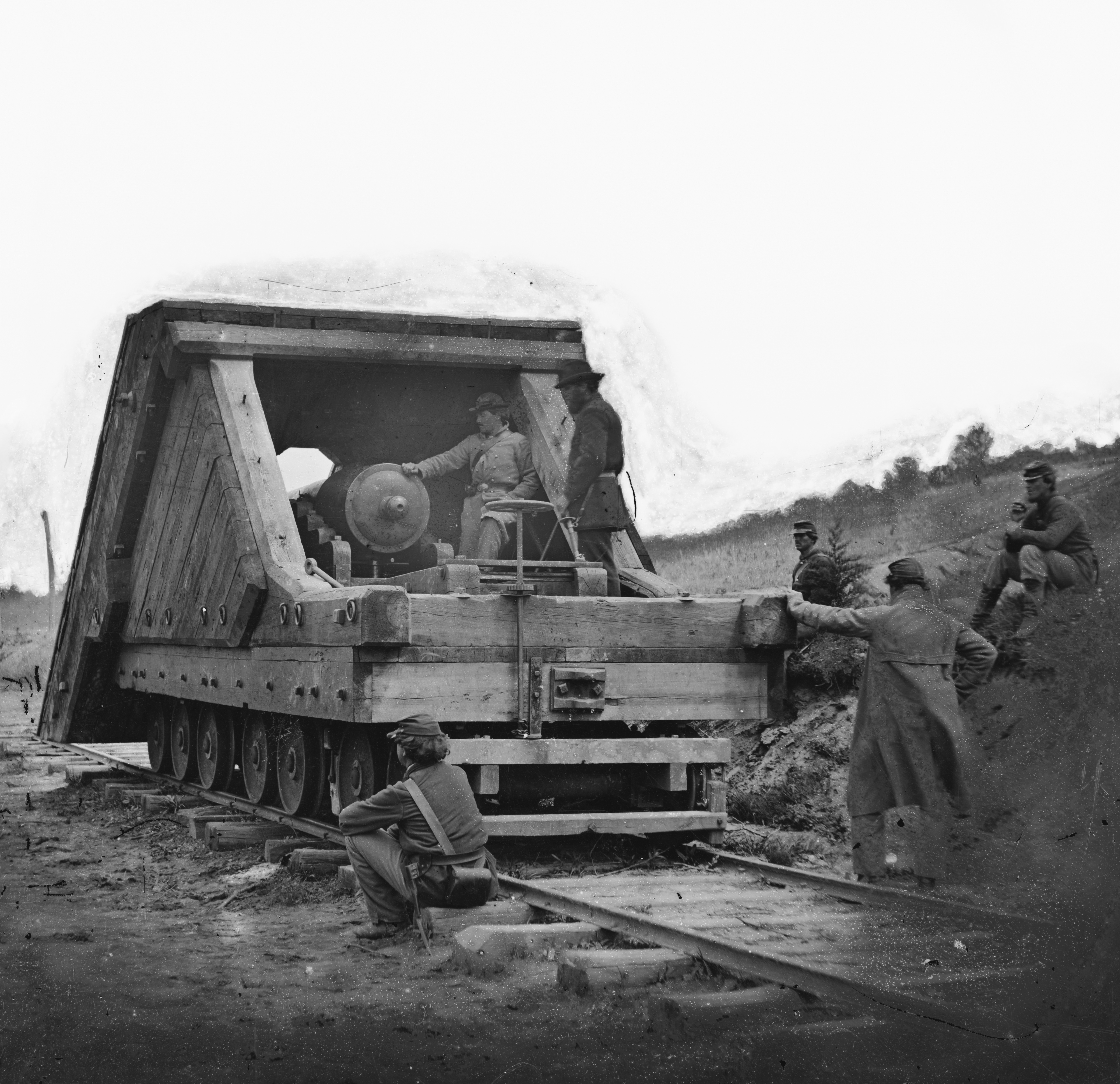
The Lee-Brooke Railway Gun. The LoC has a high resolution
 copy of this image.

Since I don't have enough to do, I added some more projects to my do list. The first is a model of the Lee-Brooke Railway Gun in 1:32 scale to match the Dictator mortar model I had made previously.  These two models will be on display at the B&O Railroad Museum next year. The Dictator is done, but the Lee-Brooke Gun has to be finished in a few weeks.

I plan to document the Lee-Brooke Gun construction in more detail in my book, but I posted some in-progress shots here. This is a tricky project as only two photos exist of this gun and many details are not visible. Dr Dave Schneider, of SMR Trains, did a good job of researching the gun and some of its construction details, but there are still many unanswered questions.

I was able to get good measurements of an existing rifled and banded Brooke 32 pound 57 cwt cannon at the Navy Yard in Washington.   I machined the model gun from brass rods. The main tube, trunnions and knob are separate pieces. Being brass they were easy to solder using my torch.

Using the gun dimensions and the rail gauge visible in the photo, I was able to scale most of the other dimensions of the model from the photos.

Brass cannon
I concluded that the plans in Alexander's book, while very good for overall proportion are off by about 50 percent. He assumed that the wheels are 33 inch wheels. But they are smaller, probably closer to 26-28 inches. I used 42 inch O scale wheels from NWSL (thanks are due to Derrel and Linda at NWSL for the rush job in shipping the wheels to me.) These scale out to 28 inches in 1:32nd scale.

I machined axles out of iron rods. The trucks are laser cut wood and plastic. I used photo etched brake parts from my O scale cars to fabricate the brakes for the rear truck.

Trucks and frame before decking.

I decided to make all the wheels on pivoting trucks based on the truss rod patterns on the side frames. They indicated to me that the front truck was similar to the rear two trucks. It is moot since in normal viewing, you really can't see the trucks. I also added the truss rods on the frame even though they are not visible from above.

It should be noted that this car has no evidence of longitudinal truss rods. I suspect that the lengthwise planks  as well as the heavy wood framing for the ironclad casement also serve as the the longitudinal stiffeners. I originally added longitudinal frame blocking, but removed them after reconsidering the location of the truss rods. I probably should have added two lengthwise beams and used transverse blocking. Oh well. I will change that the next time I do it, maybe in O Scale.

The gun carriage was really a dilemma, as I could find no other cannon with a carriage like this one. It looks to me that they took a seacoast casement  carriage from a fortress and modified it to fit. It appears to be a cross between the casement carriage (Plate 10 US Army Ordnance manual) and the carriage for flank  casements (Plate 11 US Ordnance manual). But many of the visible details don't match either of those guns. The number of steps on the side walls, the screw elevation and the type of gun are different. The Plate 10 carriage is close but there is no tongue on this gun, and the wheel tracks on the rails are different. In fact, the wheel tracks are not visible in the Lee-Brooke Railway Gun photo, but I assumed they are there and hidden by the view angle of the photo.

Gun and carriage sitting on chassis. The casement is
started.
So the approach I took was to copy all the detail that I could see and then did a little imagineering for the rest.  Based on the angle that the carriage rails sit on, I suspect it may have some type of pintle giving it a limited traverse.  I plan on adding that feature.

Given the dearth of information, any suggestions would be appreciated.


October 28, 2012

Meanwhile, back on the layout...

Hurricane Sandy is bearing down on the Mid-Atlantic and we are all standing by hoping it will spare us. With our storm preparations complete, I thought I would do a blog post to catch up some loose ends.


Last month I did a quick scratch build of a simple cook house for the tavern scene. The idea for the cook house came from some books I borrowed from Gerry Fitzgerald about vernacular architecture. In particular the book, Back of the Big House: The Architecture of Plantation Slavery (Fred W. Morrison Series in Southern Studies) was very handy. I based my building on a similar structure from this book. This building houses a kitchen and servants quarters. The servants were likely slaves before the Union Army arrived. The building is now being used by the Army as a kitchen and Quartermaster office.

I used Tichy windows and scribed siding. The roof shingles are laser cut red cedar with self-stick adhesive. The chimney is a simple scratchbuild from sheets of brick paper over a wood core. Due to the steep hillside, I had to install the building on wooden pilings.
The cook house uphill from the tavern

To complete the tavern scene I will also add a well house, cold cellar, hitching post and other details. I started adding some fencing, but more of these will be required. I also need to paint the backdrop in this area.

Edwin Alexander's figures
A photo from Alexander's book showing some of these
figures on his layout.
Yesterday I received in the mail and package from John Brazaitis containing 6 O scale figures. He purchased these figures from Edwin Alexander near forty years ago.

This is a real treat for me, because about 20 years ago I purchased a copy of Alexander's book, "Civil War Railroads and Models." I saw it on the discount table at Crown Books (now defunct) and purchased it.  Since then I  have studied and examined this book endless times so that the binding is worn out and the pages are coming loose.  In large part it was my inspiration to try some Civil War Railroad modeling. So I am very grateful to John for sending me these figures. I look forward to painting them and adding them to a prominent place on the layout.

Lets hope we have a home and layout to come back to after the storm passes over.


October 27, 2012

Exploring Expansion

The Road Show project is well under way, but I took some time tonight to flesh out some ideas that I had been thinking about for several months. I was motivated by the fact that the Road Show is currently occupying the same area that these expansion ideas would. Thus the Road Show demonstrates the feasibility of a layout expansion in this foot print.

I drew up two plans, one focusing on Alexandria and a second that expands the Aquia Landing area. I did not draw up the third plan I mentioned in the previous post as it would involve ripping out the current Falmouth section. That section is operating well, even with the tight turn back curve. So there is no burning need to replace it.

Extend Burnside Wharf

Alexandria
Of these two plans, I seem to favor the extended Burnside Wharf. I like the simplicity and  uncrowded look. I also like how it allows me to make the wharf at Aquia Landing bigger and closer to the actual wharf in appearance.

As much as I like Alexandria, that plan just seems too crowded to me. Although it  is more complicated than the Expanded Burnside Wharf plan, it would still only add one operating position to the layout. It might be possible to have two crews work Alexandria, but I think they would get in each others' way. 

I will be thinking about this as work on the Road Show and other projects progresses. No decision is needed just yet.


October 25, 2012

It is lit and fits!

Even temporarily clamped up the LED Light strips do a good job illuminating the layout.
I did some furniture rearranging in the basement and made room for the ACWRR Road Show to fit along the back wall. This includes all five sections. Having all the sections set up will make the track laying and valance fitting easier.

This also confirms in my mind that if I want to expand my USMRR Aquia Line layout, the perimeter wall around the basement can be used with relatively little intrusion into the TV viewing area. My long term plan is to build custom bookshelves along these walls. The book shelves would house the AV equipment as well as have storage space for media, books and some glass encased areas for displaying models. The shelves would have a flat space about 48 inches off the floor that would used for future layout projects. Whether it will be an expansion of the current layout or a completely new project I haven't decided.  Three possible expansions of this layout include extending the Burnside wharf to this area, adding a completely separate scene depicting Alexandria and connected by car float, or expanding the layout under the starirs and relocating Falmouth to this space. Or building a completely unrelated layout. Two themes that are possibilities are a steam era steel mill or a layout depicting the Alexandria waterfront and shipyard in WWI.

Virginia Shipbuilding Co in WWI

The whole layout fits along the back
wall of the basement.
But back to the road show, I took delivery of the LED strips yesterday. I tried some low current power supplies I had on hand and they did not do a good job of lighting the LEDs. So I hooked up the higher rated power supply that I ordered along with the LEDs. That required me to fabricate a 110V power cord. I had one on hand so it was a simple matter to hook it up by adding some spade connectors. With this power supply providing 12V and sufficient current, the LEDs are brightly lit. By using two strips of LEDs the layout should be well lit. The LEDs weigh next to nothing. They come with ballast resistors installed, so hooking them up is a snap.


Thinner and slightly lower valance panels

I also tried using a thinner valance panel and lowered it so that the top was flush with the valance frames. I think this look better and will make adding a top panel easier if we decide to do that. The thinner lower valance creates an opening 14 inches from water surface to valance bottom. It will make the sections a little less bulky.  I think it creates a more finished product, as the valance won't protrude like a false front in this configuration.


October 22, 2012

A section too far?

Bill Mosteller, proprietor of Great Decals, stopped by to see the layout tonight. After a quick tour and running a train around the layout, he offered to help move the Road Show to the basement. With his and AW's help we got all the sections and tools moved to the basement. The garage is  cleared up so the car can fit back in there.

Three sections is all I can set up at one time in my basement. Anybody want a layout section?
A couple observations on moving the layout. The sections are fairly light, but they are bulky, especially the bigger ones.

The valance supports are just too tempting to use as handles.  I need to  beef them up so that they can  act as handles if necessary. The legs will need some type of locking mechanism for both the down and up positions.  There may be an existing table leg hardware solution we can modify. Bill mentioned that he was impressed with the folding legs but agreed that a locking device was needed.

October 21, 2012

Act II, The Benchwork Strikes Back

Another long day in the garage working on the benchwork.  It is almost ready to move to the basement for the finer detail work. I have to clear up the garage so the car can go back in there.

I tried to come up with a way to cantilever the valance so that the front view would not be obstructed. But I was not happy with any of the cantilever schemes I came up with. So I decided to add posts to the corners of each section. My wife and neighbor took at look at it and gave it a thumbs up. They did not find the posts too distracting. Once they are painted and the layout lighted from inside the valance, I think they will disappear.

I was pleasantly surprised to note how strong the valance with the posts turned out. They should hold up fine in shows. But I wouldn't pick up the layout just from the valance.

Under the layout, I added Tee nuts and bolts so that the sections can screw together without clamps. Two more necessary tasks remaining under the layout are to add some diagonal braces to the legs so they don't wobble and to add adjusting Tee nuts to the leg bottoms. These come in handy if the floor  at the exhibition location is uneven (it usually is).

Half inch lumber serves as valance posts at the corner of each section.

A closer view of the posts with a box car and paper structure mock-up for perspective. The valance panels are
not secured yet, they are just clamped on.

The narrow sections  (18 inches wide) still have plenty of room for scenery. A good backdrop will be important.
I added the sky board panels to the back. They are 16 inches tall. The opening from the valance to the water level is also 16 inches. The track will be 2.125 inches above water level.

October 20, 2012

The Show Begins....

After one day's work - twenty feet of ACWRRRS benchwork with folding legs.
Morning run to Lowes and Home Depot
B-Day has arrived!   Brian Brendel and Gerry Fitzgerald showed up with bags of power tools while I brought home a truck load of lumber and hardware to begin building the ACWRR Road Show (ACWRRRS). In about 8 hours we had completed the benchwork and legs for the first 5 sections.

We referred to the scale model mock-up several times and actually modified the design by examining and discussing the model mock-up. It proved very useful.

We used 1x4 clear pine frame members with 1x2 stiffeners and 2x2 legs with gate hinges.  The top surface of each section is a flat surface made with 1/4 inch plywood (actually premium underlay panels ). All the legs fold into the 4-foot sections. Each section weighs about 5 pounds and are quite sturdy. We used Kreg Pocket Jigs to attach the butt joined pieces creating a neat finished  appearance. The legs will get leveling Tee Nuts on their bottoms.

We are still testing  the sky board and valance geometry.  We had 12 inch sky board sections ready to go, but now we think we need a taller sky board. Fortunately, all the sky board sections were cut from a single piece of 1/8th inch tempered hardboard and cost only $8.50, so that won't hurt too much if we can't use them.  In fact,  the whole project has cost about $230 US so far.

A few more hours of finishing details and the benchwork will be done. The best part is that since we are using battery power, there is practically no wiring necessary. The power supply for the LED lights will also supply power to the trickle charge on the rails. Given that we hate wiring, that is great news.

Brian and Bernie work on the first section deciding the final construction details

Finishing up the first set of folding legs.

The first two sections set up to test height and stabilty. Most sections only have one set of legs, except the
big end section, which has two.


Gerry attaching the second set of legs to the biggest (widest) section

Bernie and Gerry posing by four of the 5 sections.  It is too long to set up all 5 sections in the garage.

October 18, 2012

Scale Model Mock-Up

Mock-up of the road show
As B-Day* approaches I thought I take some time to do a more detailed mock-up of the ACWRR Road Show to see how everything looked in 3D. I made a scale mock-up of the layout in 1/2 inch to the foot scale. Since it is an O scale layout, that works out to a model that is 1:1,152  scale.

The mock-up you see at the left is first mock-up we made based on an earlier design. This mock-up was not as detailed, but it convinced us that the design was too wide. So that help lead us to this long-linear design.


I used my laser to cut the pieces of the layout on various scrap wood and task board. I also used the laser to cut some more detailed parts like the trains, track, truss bridge and boat. The buildings and barge are pieces of scrap trimmed to rough size and shape.

Looking at the mock-up led me to change a few things. I got rid of the notch on the far left. That meant extending the side backdrop panel to the front. That will help support the valance on that end. It also allows a little more room for the boat.

I also made the notch in the river in the middle more shallow. I think it looks better.


The shipyard buildings add a nice sense of mass to the center, though it will be tight to try to fit the marine ways between the track and the layout edge. If the vessel under construction is a barge, it will make it easier to fit in.

I used a little ground foam to simulate trees on the far right. They hide the entrance to the fiddle yard, which may be as simple as one piece of track or as elaborate as a traverser mounted on a cabinet slide. That is TBD.

Most of the valance panels will be cantilevered over the layout. The LED light strips are super light, but the valance should be stout enough that if someone leans against it it will hold up.


* B-Day = Benchwork Day

October 15, 2012

Civil War Road Show Update

The design for the ACWRR Road Show is solidifying as this weekend approaches when Gerry and Brian plan to come over to help me build the benchwork for the layout.

This evening I did a few modifications to the plan to accommodate the latest developments. Here is the updated track plan.


First, I drew the ship that we plan to build, the QMD Clinch,  in full scale. It will be about 38 inches long and 7 inches wide. Since it was a little bigger than originally planned, it required some modifications to the waterfront. I could not decide if we should keep the ship on one section so that it would be protected by the benchwork and valance during shipment, or use its hull to disguise the sectional joint.  It will fit either way.  As I mentioned earlier, Andy Small will be building this ship.

I also drew in a floating warehouse up stream from the steam boat. These are neat structures and should be relatively easy to build.

I notched the bench work on the far left to allow slightly easier access to the turntable.

At lunch today, Marty asked me about how the layout could be expanded. I had thought that an Army shipyard with marine ways  would be a neat addition.  Since Marty builds naval warships for a living (not literally but he does work on a naval radar system) I thought one of the temporary shipyards built by the US Army Quartermaster Department might be an appropriate scene.  So I added a shipyard section. This shipyard borrows elements from the various locations but especially the shipyard at Chattanooga where the USQM built an elaborate boiler shop complete with decorative cupola on the roof.  The shipyard at Chattanooga was serviced by the railroad on a switchback tracks, so this plan includes a siding.

Alternatively, a large steam powered saw mill would be a good addition for a section too.

I also extended the fiddle yard a foot to allow staging of slightly longer trains. The sidings on the layout  can handle longer trains.

Now to make a Bill of Materials and get to the lumberyard before the weekend. The first thing I ordered was a set of LED Lighting strips and a power supply from this ebay store based on Ted Dilorio's recommendation. I hope these work well. We can also use the power supply to recharge the locomotive batteries.


A Two Mile Tune Up

Up to now I had been focused on building the layout and doing scenery. I have built about two scale miles of track. I haven't spent much time trying to operate. So I had a lot of deferred maintenance. It was time to fix that.

Since the ACWRRHS Open House, I have spent some time converting all my couplers to my photoetched couplers with the open back design. I removed all of my laser cut and SMR couplers and installed my photoetched ones. I also checked and adjusted the coupler height on all my cars so they are the same. While I was tuning things up, I replaced a few wheel sets that had high friction journals. I also repaired some broken brake chains so the brakes work on cars so equipped. Then I cleaned the wheels.

I also developed a revised link, which I call the Easy-Link. I made these on my laser using resin impregnated paper, which is already a rust color, so no painting required. They are slightly narrower than the ones I have been using, so they bind less in the coupler holes. But the key difference is they have a transverse bar across the middle. This prevents them from sliding completely into the coupler pocket when trying to couple up, but does not prevent the coupler faces from pushing on each other when backing. They work great. And a laser cut fret has about a 100, so losing them is no big deal.

Next I turned to my locos. I thoroughly cleaned the wheels and pickups on McCallum, which has a Tsumani sound system with track power, and Whiton, which has a Stanton S-Cab battery system. I also ensured that the wires for the decoders and batteries did not interfere with the operation of the locos especially in the tender where excess wire was causing some binding at the drive universal joints.

Finally I cleaned the track, checked and adjusted the gauge in some trouble spots. Because some of my curves are very, very tight, I have used guard rails to help prevent derails. These are not unprototypical, they really help and are visually unobtrusive. I also have number 5 turnouts that create ess curves in crossovers. But so far they have not been a problem.

Since doing this, my layout is operating at about 99 percent reliability. The battery unit is awesome. It just chugs along. But even McCallum and Haupt are running great with only an occasional stall (maybe once per back and forth run). I am able to run 7 and 8 cars trains back and forth over the layout. So overall I am very pleased and psyched to keep pushing on.

Next weekend we start building the bench work for the ACWRRHS road show. More on that later.

October 14, 2012

Fine Scale Model Expo

A highly detailed scene from the Muskrat Ramble On30 Layout
I attended the Fine Scale Model Railroaders Expo held in Lancaster, PA this weekend. Overall the FSMRR Expo was a small, but interesting show.  On Thursday I presented a clinic on assembling multimedia kits with emphasis on soldering brass kits. We had 22 folks build an Alkem Scale Models water tank. On Friday I presented a talk on "Introduction to Railroads of the Civil War." There was a good crowd present for that.

SS Clinch on the Tennessee River in 1864
The highlight of the show was the ability to reconnect with Andy Small of the Train Troll. Andy agreed to be a sponsor of the ACWRR Road Show.  Andy is a naval architect and the proprietor  of Train Troll, a small company that specializes in ship, barge and boat models for model railroads. He has offered to build a model of the SS Clinch, a river packet ship that served on the Tennessee River and survived the war.  This is great news, as Andy is an excellent modeler, his kits are great and he is an expert on river steam ships.  Andy may also offer this model as a kit if it is commercially feasible. Welcome aboard Andy!

Any other folks interested in sponsoring or participating in the ACWRR RS, please contact me. We can use volunteers to paint figures, build structures, trees and freight cars.

Another highlight from the show was a chance for me to inspect the Muskrat Ramble layout. This is a well known layout that was built in Australia by a group of talented modelers. It came to the US for a train show and was purchased by Dave Revella. It normally resides in the Suncoast Center for Finescale Modeling in Florida.  This layout is similar  in concept to our proposed ACWRR Road Show, though is it bigger and based on a more fanciful subject, a fictional swamp scene in Louisiana.  In any case, it is a crowd pleaser with many extremely well done and highly detailed models visible.

This layout uses a variety of techniques to suspend the valance and they all seem to work. I think we have been over-thinking this aspect of our ACWRR Road Show.  It seems that if there are trains moving through well executed scenery  and past highly detailed models, one does not spend much time looking at the display infrastructure.

While I enjoyed looking at the layout, I spent more time examining the valance, fascia and  sectional joints. Some of my comments are in the captions below.

Lighting adds a lot to the display, both overall and interior.


The right side of the Muskrat Ramble contains a cotton field extending on the backdrop. It is very
convincing.  Good backdrops add a lot to a layout.
Down view angle showing the thick "flats" used along the backdrop. The simple backdrop seems to
work well behind the structures, but I wonder if more could be done at the road area.


The layout uses a variety of valance panels and supports. Almost all are unobtrusive and
nearly "invisible" even though they have joints and intermediate sections.

Trees hide the return loops as they pass through the backdrop

The sectional joint is nearly invisible in this scene both in the sky and on the ground.
A rarely photographed view of the backside infrastructure of the layout. The loops allow the
layout to run nearly unattended, a luxury we won't have with the ACWRR RS.
The paddle wheeler on the layout seemed too much like a caricature to my eye. On our display, we
 intend to show a stern wheeler packet ship in full scale size. It is a challenge to design a layout to
incorporate O Scale boats to full scale, but I think we can achieve it. 

Each individual tree on the layout is rather crude, but when used in mass they look acceptable. I think more
attention could have been paid to the foreground trees.


October 9, 2012

Road Show Design Tweak


I tweaked the road show design a bit. By making the left side a tad wider, I was able to tilt the tracks some more to make room for the turntable. With the engine terminal on the left end, the depot had to relocate to the right side. In this location it be a half-flat model to the gable top as opposed to a full model as on the previous plan. In this location it will be  reached by a reverse move, which will add some switch interest.  With the run around and turntable that won't be a problem.

The depot track can hold three cars.

There was also room for an engine storage track on the other end with a water tank and wood rick.

The three-way turnout is not required. There is room to make it sequential turnouts if a three-way is problematic.

It all still fits on 4 ft sections. So buying lumber is  snap. Also, 4 ft sections will be easier to fit in a smaller SUV if we get one like my wife is talking about.  If anything needs to be a little longer it's the fiddle yard. An extra foot there would help allow 5 car trains and an engine.