A journal following the history, design, construction and operation of Bernard Kempinski's O Scale model railroad depicting the U. S. Military Railroad (USMRR) Aquia-Falmouth line in 1863, and other model projects.
©Bernard Kempinski All text and images, except as noted, on this blog are copyrighted by the author and may not be used without permission.
-----------------------------------------------------------------------------------------------------------------------------------------------------------------
Showing posts with label Ironclad. Show all posts

January 1, 2013

B&O Ironclad Car -- Take 2 (or 3 or 4?)

I was not happy with the earlier model.  So I tried again. The armor should be railroad iron. So it should have a "Tee" rail profile, not a rectangle. I was using code 55 rail to simulate the armor, which is close to the scale size, but is very fine.

I tried several techniques to secure code 55 rail to the sides of the car to simulate the iron armor. On the fourth try I decided to use two-sided transfer tape. That make sticking the iron bars easier to position and reposition if necessary. It also prevented glue globs from showing between the rails. I used the laser to engrave a set of lines to help in the spacing. Even with that the rails did not line up perfectly, but I think it helps the model.

The two finished cars compared. A couple others ended up in the trash.
The transfer tape is quite permanent. The rails are secure enough, especially for a static model.

As for colors, we don't know what they actually were. The dark gray armor on freight car red looked good to me.

So this is the version that will go to the B&O Museum. The earlier version will go on my layout for escort duty.

A slightly revised rear end.

The business end with the gun port cover. The cover was operated by a lever inside the car.

December 30, 2012

B&O Ironclad Car Finished


I finished the B&O ironclad car except for the gun port, some minor clean-up and touch up. I had trouble finding a good way to simulate the iron rail armor. It sounds simple, but getting the code 55 iron rail to create a realistic appearing armor in 1/48 scale was not easy. I tried four different techniques but ended up using a laser cut taskboard layer for the armor with separately applied bolts and washers that I laser cut. I did not use the first model I made shown in the previous post.


I added some barrels and boxes inside the car. There is also a field gun inside.
Add caption

Next is the B&O box car with the infantry firing ports.

December 25, 2012

B&O Ironclad Cars

I started building 1/48th scale models of the B&O Ironclad and Rifle cars.  These models are destined for the B&O Museum collection.  I am working with Dan Toomey of the B&O Museum to try to make these models as accurate as possible, but given the limited and conflicting information we have about the cars, much is educated guess work.  For example, there are several descriptions of an engagement where one of these cars was destroyed. Each account has different descriptions of the car and its construction. Most of them are summarized at this web site . It's is hard to know which one is right.

The cars are described in Alan Koenig's dissertation, "Ironclads on Rails: Armor Returns to the Battlefield, 1861-65. This was our main source as it cites several statements from the builders, as well as  observers that saw the car in service or after it was destroyed.

The ironclads are also mentioned in Robert Hodges, Jr.'s book, "American Civil War Railroad Tactics." The latter includes an artist's concept painting of what the cars may have looked like as no known images of the cars have survived.  While we agree with the overall look of the cars in the painting, there are certain details we will change.

The drawing shows our interpretation of the cars. The approach we used is to assume they started with standard boxcars and added the armor as an applique. These cars were built quickly, so it seems likely they started with existing parts if not whole cars.

According to Koenig, one source says the armor was mounted on a 45 degree angle. That is possible on the front of the car, but not possible on the sides as it would make the car too wide. So we made the side taper more vertical.

Koenig lists one source that states the rail was "T" iron, while another just says "railroad iron." We elected to go with "T" iron, in the form of code 55 rail, which works out to 2.6 inches in full scale. At this point most major railroads were installing 60 to 70 pound per yard rail on their mainlines, which scales down to about code 90 (0.093 inches inches tall). So the rail on this car represents lighter rail that was either destined for yard use or was retired. I had a bunch of code 55 on hand, so I used it.

Is code 55 reasonable? Yes, because heavier weight rail would have overloaded the 10 ton capacity of the car,  which was typical of a box car of the civil war era on two trucks.  The table illustrates that at 30 pounds per yard of rail the car would weigh about 10.2 tons loaded with crew, gun and ammunition. Even rail at 40 pounds per yard would have overloaded the car by 30 percent.
Heavier 60 or 70 code rail would have seriously overloaded the car. (Note that the number of rails per side for larger weight rail would be less than shown here as the the heavier rail is also wider. But the weight increases with the cube of the size, so the weight gain will out-pace the width related savings.)
"T" Rail added by the crew to protect the casement corner on USS Cairo

Some sources say the rail was spiked on, but Dan believes that it was bolted. I used the railroad T armor on the restored USS Cairo as a guide for how such rail would have been bolted on. In the case of the USS Cairo, the rail was bolted with the flat side facing out. I reversed it on the car as it was too hard for me to get the code 55 rail to look correct in that configuration. It would not lie flat as I assembled it.

Most sources state that the cars were equipped with one gun each, mostly small mountain howitzers, but one had a 6 pound brass smoothbore.  The first versions of these cars had cannon mounted in the vehicle suspended from the roof with a series of ropes. But later versions used standard field carriages as we show here.

There is a gun port on the front of the car. The artist concept in Hodge's book shows gun ports and cannon pointing out the side, but the car is too narrow for the standard field cannon to fire to the side. So there is no point to have gun ports on the sides, though there may have been observation ports. We elected to include 3 loop holes on each side instead of additional gun ports.

These cars were operated in sets. An armored train would have ironclads on front and back, with rifle cars between the ironclad and the locomotive. So a gun pointing out from each end of the train might be effective in covering the area around the train, especially if the gun could cover a 60 degree arc from its embrasure.

The gun port was reported to be 6 inches square, but again that is unlikely as such a small size would not allow the gun to defect or elevate very much. The gun port must be a bit bigger. One source, Deffinbaugh, claims he found the gunport of the destroyed car and that it was a solid piece of iron.

The last puzzle was the rear of the car. Again according to Koenig, one source says the rear was also sloped with an embrasure for a gun. But most other sources say that only one gun was mounted in each car. If you put a 6 pounder smooth bore on a standard field carriage on a rail car that can travel along standard gauge tracks, there is no way the car can be wide enough to turn the gun around inside the car.  So one gun cannot serve both gun ports.  It seemed impractical to me for the car not to have a decent size access door, so I added one to the rear.

One of the problems I have noted with some artists' concepts and drawings of artillery mounted on flat cars is that they make the gun carriage too small in relation to the car. The drawing above shows both the gun and car in the same scale.  As you can see, a 6 pounder on a standard field carriage just barely fits in the car. There is some room to deflect the cannon right or left to aim, but firing off the side is not possible.

We welcome your comments or ideas. The famous ship historian and modeler Howard Chapelle once said words to the effect that you should never build a model until you have all the information you need, as others that view the model will not know where you guessed. (for more of Howard's argument see this link.)In this case, we recognize that the information is sketchy about these cars and do not claim that this is a 100 percent accurate representation of the car, but the best we can make.  We hope you enjoy it.


December 20, 2012

Rail Gun Encased

The Land Merrimack posed on my O Scale layout.
I added a diorama pedestal base and acrylic dust cover to the rail gun model. The base is a solid plank of cherry that I cut and routed into a base. It matches the base for the Dictator diorama. I still haven't perfected the acrylic case technique yet, as I got a glue stain on the top surface. But it will serve the purpose of protecting the model from dust and fingers.

The section of track is code 100 rail on hand carved poplar and basswood ties. I added some grass tufts and various leaf and pebble texture to the soil. All it needs is a laser cut name plate and it is ready to display. I haven't decided if I should add a figure to the diorama. It might help provide a sense of size and scale. The model is built to 1:32nd scale.


December 13, 2012

Rail Gun - Finished


I finished up the remaining details on the rail gun. I replaced the coupler on the rear. The first one was too big.  Since I laser cut the parts from 1/16th inch acrylic, it was a simple matter to reduce the height of the center part and and reinstall it. The nut detail is actually engraved. The coupler simply is glued to the wood frame.

The brake wheel hangers were the next challenge. I made the parts from 0.020 inch strip brass, a .042 inch brass rod and an etched brass wheel from my spares box. To fashion the parts I used my drill press with an x-y table to drill holes in a straight line. Then I used a new sharp  file to shape the parts. I secured the parts to the model and then added NBW details with CAA. I added a cast white metal gear to the shaft to represent the locking pinion.  To simulate the pawl, I added a small silver of wood.

I had to use brass for the parts  because the next step involved soldering the brake chain to the wheel shaft and the brake linkage on the truck. With everything soldered up, I tested the brake mechanism. It does work, though it would need some adjustments if this were to be an operating model.

Next I added an elevation wheel to the gun (not visible in these photos). I also mounted a small rod on the bottom   front of the gun carriage and added a wood strip with an iron strap on the rear. This allows the gun to deflect a limited amount in the casement while also tilting the gun forward. The tilt allows the gunners to run the gun out for firing, while the up slope helps absorb some of the recoil.

Next I must build the base to display the gun, and an acrylic case to protect it.


Having studied this gun, I am convinced that it was built solely as a weapon to counter other rail mounted iron clad guns. The heavy 32 pound cannon is impractical as a field weapon against mobile infantry and artillery targets. The limited traverse also hinders its use as a general field piece. The heavy armor only on the front meant that they did not expect it to be engaged from the sides.

To my mind the design of this gun supports Dr. Schneider's thesis that this was the "Dry Land Merrimack" that Lee had Brooke build for the Peninsula Campaign in 1862. They built the gun as a response to reports that the Union were also developing an ironclad  railroad gun. The Lee-Brooke gun was used once, probably found impractical as the Union did not have a matching railroad ironclad, and then retired to a siding, where it was discovered a few years later by Union soldiers.

December 12, 2012

Rail Gun Update

I am almost finished with the Lee-Brooke Rail Gun. Here are some shots showing the model. I attempted to add any detail visible in the two existing photos. Everything on the model except the wheels has been built from scratch.

The iron armor is laser cut and engraved acrylic.
I still need to add the brake wheel and the cannon elevation wheel.  With the brake wheel installed, the brakes will work.

I plan to make a solid cherry pedestal and acrylic case for it to match the existing Dictator mortar model. These will be on display at the B&O Museum next year starting in January.


October 30, 2012

Lee-Brooke Railway Gun

We made it through Hurricane Sandy with no damage. Our power flickered a few times, but it stayed on. Our sump pump was working nearly continuously and it did its job. We have battery back-up on the pump, but I am thinking a generator might be a good investment. Without that pump, the basement and layout would flood.

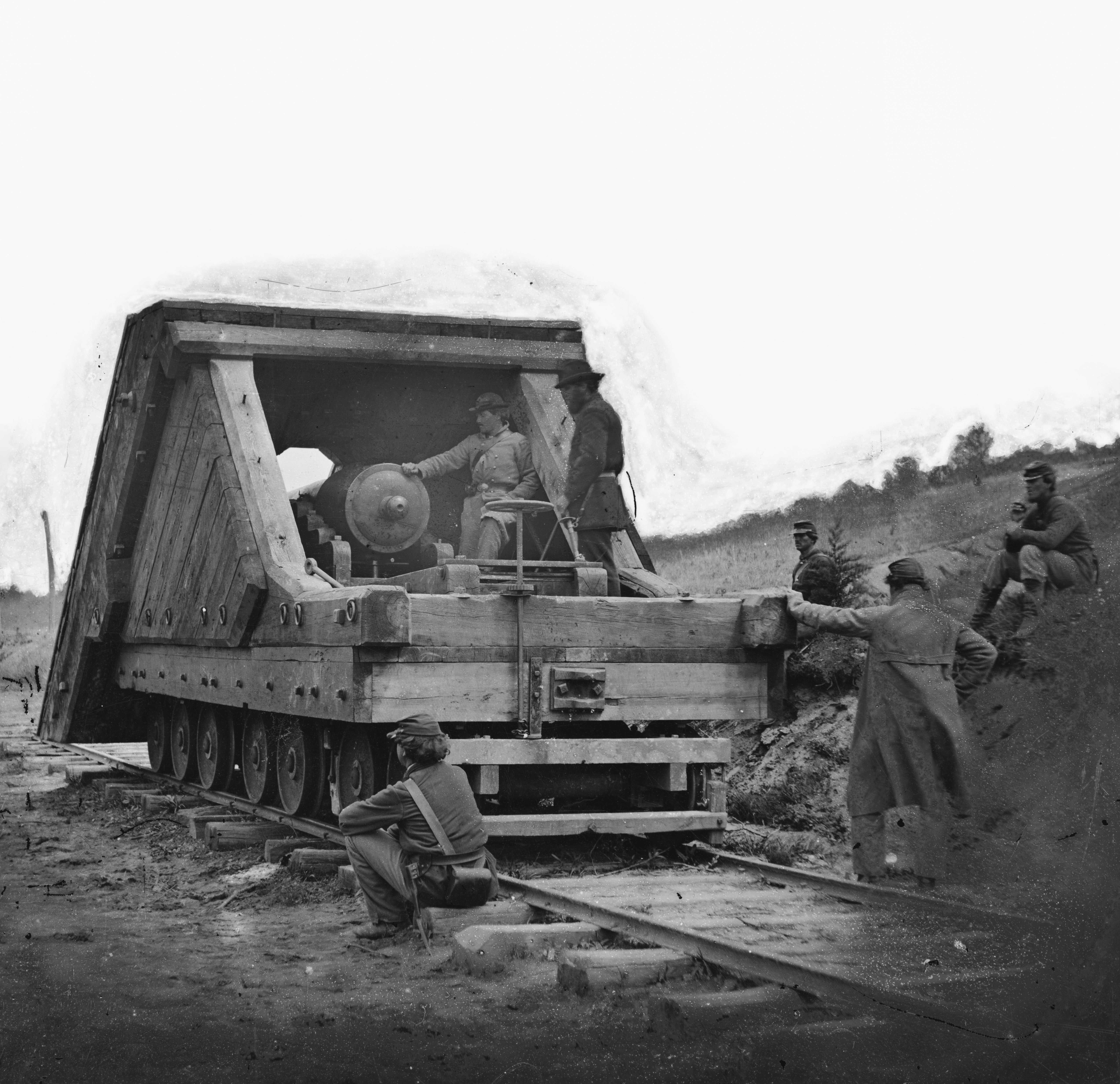
The Lee-Brooke Railway Gun. The LoC has a high resolution
 copy of this image.

Since I don't have enough to do, I added some more projects to my do list. The first is a model of the Lee-Brooke Railway Gun in 1:32 scale to match the Dictator mortar model I had made previously.  These two models will be on display at the B&O Railroad Museum next year. The Dictator is done, but the Lee-Brooke Gun has to be finished in a few weeks.

I plan to document the Lee-Brooke Gun construction in more detail in my book, but I posted some in-progress shots here. This is a tricky project as only two photos exist of this gun and many details are not visible. Dr Dave Schneider, of SMR Trains, did a good job of researching the gun and some of its construction details, but there are still many unanswered questions.

I was able to get good measurements of an existing rifled and banded Brooke 32 pound 57 cwt cannon at the Navy Yard in Washington.   I machined the model gun from brass rods. The main tube, trunnions and knob are separate pieces. Being brass they were easy to solder using my torch.

Using the gun dimensions and the rail gauge visible in the photo, I was able to scale most of the other dimensions of the model from the photos.

Brass cannon
I concluded that the plans in Alexander's book, while very good for overall proportion are off by about 50 percent. He assumed that the wheels are 33 inch wheels. But they are smaller, probably closer to 26-28 inches. I used 42 inch O scale wheels from NWSL (thanks are due to Derrel and Linda at NWSL for the rush job in shipping the wheels to me.) These scale out to 28 inches in 1:32nd scale.

I machined axles out of iron rods. The trucks are laser cut wood and plastic. I used photo etched brake parts from my O scale cars to fabricate the brakes for the rear truck.

Trucks and frame before decking.

I decided to make all the wheels on pivoting trucks based on the truss rod patterns on the side frames. They indicated to me that the front truck was similar to the rear two trucks. It is moot since in normal viewing, you really can't see the trucks. I also added the truss rods on the frame even though they are not visible from above.

It should be noted that this car has no evidence of longitudinal truss rods. I suspect that the lengthwise planks  as well as the heavy wood framing for the ironclad casement also serve as the the longitudinal stiffeners. I originally added longitudinal frame blocking, but removed them after reconsidering the location of the truss rods. I probably should have added two lengthwise beams and used transverse blocking. Oh well. I will change that the next time I do it, maybe in O Scale.

The gun carriage was really a dilemma, as I could find no other cannon with a carriage like this one. It looks to me that they took a seacoast casement  carriage from a fortress and modified it to fit. It appears to be a cross between the casement carriage (Plate 10 US Army Ordnance manual) and the carriage for flank  casements (Plate 11 US Ordnance manual). But many of the visible details don't match either of those guns. The number of steps on the side walls, the screw elevation and the type of gun are different. The Plate 10 carriage is close but there is no tongue on this gun, and the wheel tracks on the rails are different. In fact, the wheel tracks are not visible in the Lee-Brooke Railway Gun photo, but I assumed they are there and hidden by the view angle of the photo.

Gun and carriage sitting on chassis. The casement is
started.
So the approach I took was to copy all the detail that I could see and then did a little imagineering for the rest.  Based on the angle that the carriage rails sit on, I suspect it may have some type of pintle giving it a limited traverse.  I plan on adding that feature.

Given the dearth of information, any suggestions would be appreciated.


May 7, 2012

Spin casting

Vulcanizer, melting pot and spin caster set up in my shop
First rubber mold


(For some unknown reason Google has been deleting images from my blog. I do not know why this is happening. Sorry for the inconvenience.)

Last year I ordered a spin casting set-up from Conley Casting Supply, in Warwick, RI. It took several months for the machines and supplies to be delivered. Then I had to make some master parts to try to cast, which required a new Sherline lathe and drill press. Last weekend I finally got it all going making my first mold and cast parts.

The mold process went well. The silicone rubber cures at 300 degrees, so it is possible to use acrylic masters.

I made three types of cannon barrels: 12 pound Napoleon, 3 inch Rifle, and a 10 pound Parrot rifle, a set of cannon wheels and stanchions for my model of the Ironclad Passaic. I added some of my PRR signal targets as I am out of stock of my brass ones.  I also put some out of production parts from other manufacturers in the mold to see how they worked out. These were wooden barrels, a switch stand and a figure.

Once I had the rubber cured, I inspected the mold and removed the masters.  I had a little rubber stick to the hub area of the wheels, but otherwise it worked great. I made a mistake and forgot to insert the center plug for the pour hole when I set up the mold. That was a minor problem that I corrected by cutting the pour hole. However, it did leave the mold thinner and therefore weaker and the rough bottom of the cut out area created some turbulence that affected the mold filling.

Then came the tricky part of cutting gates and vents. I tried cutting the gates on the bottom and the vents on top, but that was much harder than I expected as I inadvertently ended up with some gates crossing over vents,

Next I melted some pewter. I loaded the mold in the spin caster and poured the metal. At first only one cannon barrel filled. So I cut some more gates and kept pouring. As the mold warmed up, I got better yield. I also increased the spin speed. After about 30 pours I have the parts in the photo above. The pour hole of the mold started breaking up and the fill rate was not as good, so I may need to retire this mold.

Overall there was almost no flash and the the shrinkage was negligible. There was some squash distortion.  I never did get the PRR signals to fill properly. The parts are just too thin. But everything else worked pretty well.  The cannons had the best yield. They had direct gates. The side loading gates did not fill as well.

All in all a good first test. The cannons will be an Alkem Scale Models product. As no one currently makes true 1/48th scale ACW field artillery. The chassis will be laser cut wood with separately applied detail parts.  Here is a photo of a pilot model gun in a revetment at Potomac Creek. I still need to do some tweaking of the details.


March 12, 2012

Williamsburg Trip, Day 2 Mariners' Museum

Worm fence in Colonial Williamsburg
Like Day 1, Day 2 dawned bright and clear.  I went for a morning run through Colonial Williamsburg. I forget how wonderful that place is. I didn't see too much directly applicable to  my ACW project, though I did get a nice photo of a worm fence.


Company Street
When I arrived at the Mariners' Museum I was reminded that this was the 150th Anniversary of the Battle of Hampton Roads. When I picked the date for this trip, I knew this was happening, but I forgot.

So I was pleasantly surprised when I arrived. The parking lot was nearly full as the museum had scheduled all kinds of extra activities, especially with  reeanctors. There was also a conference going on for naval historians. There was so much going on that I am sure I missed a great deal.

ACW era camp fire
The museum had expanded quite a bit since my last visit about 12 years ago. The focus of the expansion is on the recovered USS Monitor turret, engine and other artifacts. It is great that they are doing this important work, but I got the impression that the Naval Museum of the Civil War in Columbus, GA has more information and better dioramas about civil war naval subjects. The Mariner's Museum also covers other subjects too, such as the ships of the Chesapeake, general maritime history from antiquity to current and a large display of small craft that I skipped this time as there was so much else going on. The exquisite Crabtree model collection is still there for viewing.

Cooking demonstration (and eating too!)
Numerous reenactors had set up camp around the museum.

A detachment of the 99th New York Infantry was there representing  soldiers from that unit that were on the USS Cumberland when she was engaged and sunk by the CSS Virginia. D Company of the 99th NYSV Infantry unit suffered 10 killed, 15 wounded and 7 missing in that battle on March 8-9, 1862.

The Confederate infantry had set up quite a nice encampment with a company street, stables and a mess area.

An African American woman demonstrated cooking techniques. A blacksmith and gunsmith also were conducting demonstrations.

There were representatives from the US Colored Troops, Signal Corps, Naval Officers and seamen from both sides, and a Confederate artillery battery from Norfolk, which is still active as a U.S. National Guard unit.

Inside there were several other special exhibits including a group trying to make a park or trail connecting the ACW entrenchments near Yorktown, women sewing period clothing, museum staff advertising their research capabilities, people hosting quizzes (I got 100 percent right), a couple authors signing books, representatives from NOAA displaying work to make the Monitor wreck site a Federal Preserve, a group dedicated to shipwrecks of the mid-Atlantic,  reenactors of the ACW era Christian Commission,  and a spy hunt for kids.

(If you are in any of these photos and would like your name to be listed, please send me a note.)

One of several Monitor Turret mock-ups on display


Detail of a stanchion used on an ironclad
A gun from the Monitor being conserved


Signing up recruits


USN Reenactors on the full-scale outdoor mockup of the Monitor

A couple posed for their photo

Norfolk Light Artillery Blues firing a 12 pound howitzer at reduced charge

I shot some video too and plan to post that later this week or next.

November 2, 2011

Thinning the herd

Alicia and I went on a purge after the flood, getting rid of many books, magazines, boxes and odds and ends that we just had hanging around. Most significantly, I gave away over 67 years of accumulated magazines. Marty got the complete CV HO Scale Coal Dock Diorama for use on his layout. JD and Brian got several of my N Scale structures that I have left over from other projects. I purged so much stuff that Alicia actually asked me if was clearing out stuff because I am terminally ill and not wanting to tell her. Not as far as I can tell - thank goodness.

As part of this clean-out I decided to sell some of my oNeTRAK modules. These were my Afton modules set featured in Great Model Railroads last year and in N Scale Railroading on a couple occasions. The buyer lives near Chicago. He made arrangements for Bill Carl to haul them out for him during the Trainfest.


I met Bill a few years ago when I photographed his club's, the Four County Society of Model Engineers (FCSME), modules for Kalmbach in 2004.


Here Bill is inspecting the burned station at Falmouth. Being a retired Army veteran who served in Bosnia, he was particularly impressed with that.

The FCSME have a bunch of extremely well done modules in HO scale.  Here are some samples of their work. They frequently exhibit at Great Scale Model Trains Show in Timonium.


Back on the Aquia Line, I took some photos of the smoke stack for the USS Passiac. I hope to get back working on the layout after CSC11. We leave in a few days for that show.

September 14, 2011

Civil War Museums in the Atlanta Area

The ACWRRHS Annual meeting included visits to two Civil War Museums with significant railroad content. We visited the Southern Museum of Civil War & Locomotive History in Big Shanty, GA and the Atlanta Cyclorama and Museum on Saturday. On Sunday I visited the Civil War Naval Museum at Port Columbus.  

We also visited the Kennesaw Battlefield Visitors Center Museum, which has a good museum for that battle and the Atlanta campaign.


  The Southern Museum was much bigger than I expected and had a variety of interesting displays, including the locomotive General, which is their main highlight. The engine is not in its civil war appearance, as it was extensively rebuilt over the years. But it was still fun to see. 


The museum also featured a display from the Glover Manufacturing Company showing tools, patterns and products from the turn of the century industry. This was really the best part of the museum as the majority of the civil war display was somewhat derivative, except for the General. 
This lathe dated to 1865

The Texas is on display at the Cyclorama museum.
It is situated in a position that makes
photography difficult.
The  Atlanta Cyclorama was very impressive. It compares favorable to the Gettysburg cyclorama.

The Gettysburg Cyclorama appears fresher, is better lit and has a better light show animation. The Atlanta cyclorama is bigger and the 3D diorama is much more elaborate. To view the Atlanta cyclorama one sits on a rotating set of seats, while at Gettysburg, you are free to move about.

Both cycloramas are worth seeing and I enjoyed seeing this one. The museum had a nice selection of Rick Reeve oil paintings but was otherwise fairly modest.
A view showing 3D figures and how they blend into the painted cyclorama.  The 3D figures are different
scales to create forced-perspective.

Civil War Naval Museum at Port Columbus was the best of the four museums I visited. It had been moved from the location where I last visited several years ago to a bigger location nearer the river. The museum also expanded and included some very impressive full-scale dioramas including the USS Hartford, the USS Monitor and the CSS Albemarle.
The CSS Albemarle at a wharf. This was an impressive diorama.
Interior of the CSS Albemarle diorama
Admiral Farragut in his stateroom in the USS Hartford full size diorama.
Dahlgren gun collection outside the museum.
These models were used in the movie, "Ironclads." In the background is the recovered remains of the
 CSS Chattahoochee. That ironclad was burned in Columbus, GA before being completed. Columbus
was the last point on the Chattahoochee River that was navigable.