

 |
| View looking through the machine shop. More weathering is required. |

I decided the steam engine needed a governor as that was a common feature in mill engines. The governor helps keep the steam engine at a constant speed as the load changes. That is key requirement when cutting multiple machines are running at specified feed rates and powered from the same source. So I drew a governor, printed it, and added it to the machine.
I installed the boiler and steam engine in an extension to the left of the shop. That means the structure will no longer fit in the wye at Aquia Landing. So, Plan A is now out.
With all the machines installed, I added the main shaft and countershafts. Some machines get power directly from the main shaft. Other machines use countershafts.
Countershafts have to fulfill three functions. They may drive at one speed, or at two speeds, but in the same direction; or they may run at two speeds, one for driving, the other for reversal. There are different ways of effecting these movements. I opted for single-speed countershafts with machines that have stepped pulleys. I 3D printed stepped pulleys for these countershafts.
 |
| Looking through the roof at the machine shop |
 |
| Typical belt shifter design |

The belt shifters are essentially the on-off switches for the machines. To make them I soldered pieces of 0.032 inch phosphor bronze to the roughly correct shape. I curved the belt shifters slightly to follow the shape of the pulleys. I used extra hangers that I printed to install them except in a few locations where there wasn't room for the full hanger. In those cases I used blocks of wood.
The belt shifters don't spin in the hangers. They slide longitudinally to shift the belts from pulleys that are loose to pulleys that are firmly attached to the shaft. Each belt shifter was a long, tapered wooden staff that extends about 6 feet above the shop floor. Operators reach up to grab the wooden staff to engage the belt shifter. I cut those staffs using 1/32nd in birch plywood on my laser cutter. The linkage for the staffs required that I solder a short section of rod at 90˙ to the direction of the belt shifters. I used 1/8 inch square sections of strip wood to hold the belt shifters to the joists.
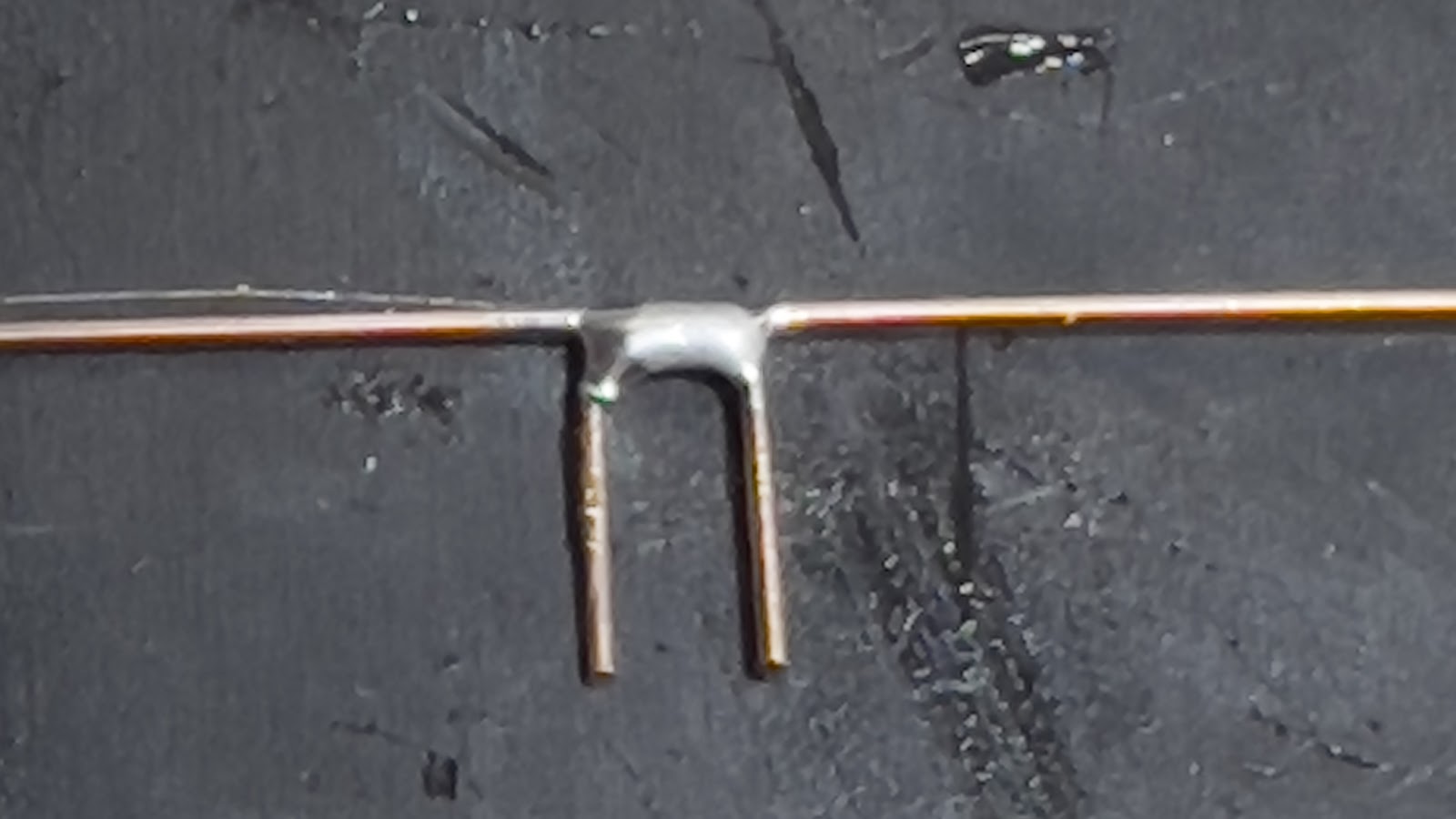 |
| Belt shifter. |
Amazing! Your attention to detail blows me away.
ReplyDeleteI hope you will enter this in a contest. The subect alone is worth a prize for originality, and the considrable detail really sets it apart. --Gary in Texas
ReplyDeleteAs a 3rd generation machinist early belt driven shops have always fascinated me. The Henry Ford museum outside of Detroit has a excellent preserved example.
ReplyDelete