

To build the telegraph key and sounder for the dispatcher's desk, I first did some searching for ideas on how to arrange the components. There are many pictures of telegraph keys and sounders available on line, but very few of them are from the civil war era. I could only find one period photo on the Library of Congress website that shows the actual telegraph instrument.
 |


I ordered some antique brass knurled knobs and screws to use as terminals for the various wires. They have not arrived yet. Once they arrive, I will finish the central panel. That is where the LED light display will be hidden behind a small door. The dispatcher can open the door to see the lights. Each station will have a light that flashes when that station is sending a message. It is not period correct, but could help a new dispatcher that is not familiar with the code. That was a feature that Seth and Steve added. I did not have it in my original spec. A nice example of defense contractors "gold plating" their systems!
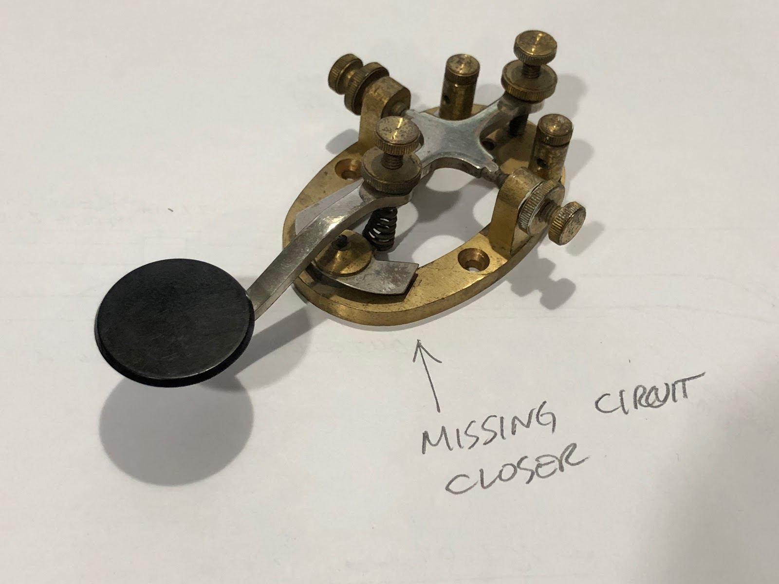
In examining my key, I noticed that it is missing the circuit closer switch. The operator is supposed to use that switch to by-pass the key, so that messages can be received. However, in our system, we plan to use the key only as a momentary on-off switch. We don't need the circuit closer, so I think this will work in this system.
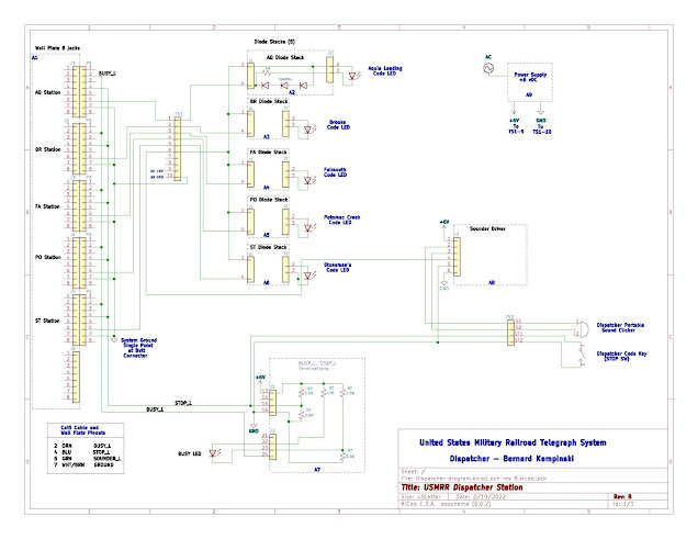
Meanwhile, Amby has been busy documenting the wiring of the overall system. There are a lot of wires and cables, but it is not as complicated as it may look. We plan to begin installing on Monday.

This is very impressive. How much telegraphy will an operator need to know to run the layout? I assume since you always cover all the bases that you will prepare something to read and study for those interested. Looking forward to the next update.
ReplyDeleteI have documented the genesis and operation of the telegraph system earlier on my blog. Here is one early post the explains the basics. https://usmrr.blogspot.com/2018/02/ripple-effect-adding-telegraph.html
Deletemore info here https://usmrr.blogspot.com/2018/12/its-alive.html
and here
https://usmrr.blogspot.com/2018/12/telegraph-system-design.html
That's just crazy cool!
ReplyDeleteThanks! The new update video is also really nifty!
ReplyDelete