 A
A question for you sailing experts- What kind of ship is docked in the foreground of this picture taken in Alexandria in the 1860s. (Click image to enlarge) It is a cargo schooner of some type, but with a slab sided, almost barge-like hull. The stern is squared off, and very "boxy". Note the next ship in the background is similar. The bulwarks are tall and solid, with no railings.
These type of ships were common cargo haulers in the Civil War, yet I can't seem to find any information about them. Most of the schooners from that era that I can find out about are either racing yachts, fishing ships or Baltimore Clippers. All have much more graceful hulls than the ship pictured here.
What is it called? Any ideas where I can get a set of plans for one?
Initial research lead me to think it may be a Ram schooner. But this was ruled out as more information became available. This is from
Bayou JournalRam schooners were an evolutionary sideline, a branch off the long line of schooners in Chesapeake history: the fast slavers, the Baltimore clippers, the big coasters that ranged from New England to the Caribbean, and the sleek pleasure yachts and racers.
Ram schooners were relatively high and “wall-sided” to increase capacity. This, coupled with their relatively shallow draft meant that they would slide sideways when sailing into the wind. While the ram’s design meant that it sailed poorly compared with other schooners, its broad, rectangular midsection was characteristic of most later sail merchant ships—a huge box with maximum cargo space.
The following NPS website has a pretty good history of the Cheasapeake Ram Schooner.
http://www.nps.gov/history/maritime/nhl/victory.htm that convinced me that Ram Schooner isn't the right answer. According to this web site, like the Chesapeake Ram Schooner has three masts. But the other attributes, such as bald head gaff rig and boxy hull, seem to match.
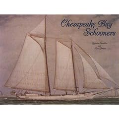
The mystery continued until I borrowed a copy of the book "Chesapeake Bay Schooners" by Snediker and Jensen from the LoC.

It has all the info I need to build a appropriate model. These were not Chesapeake Rams. A quick read of the book indicates that a two-masted centerboard freight vessel were simply called "Chesapeake Bay Schooners." Mystery solved. I ordered a copy from Amazon.
The design was a development of the Baltimore Clipper, but with a full bodied hull for more cargo. Many had centerboards for operation in shallow water. According to Chapelle, a Chesapeake Bay schooner had a straight keel, an upright, flaring stem, a round tuck, and a square stern with a upper and lower transom. She had a flush deck, a short but unusually sharp convex entrance, and a rather long, fine run. Her midsection was characterized by a floor that had a slight rise, a low round bilge and some tumble home in the topsides and a long exaggerated cutwater. However, Snediker goes on to say that surefire identification was impossible due to many local variations. Fortunately, his book has several plans suitable for model building.

 I was thinking about the previous layouts I had started in my current layout room and was wondering how it was that I was able to fit an O Scale layout in this space. That inspired me to take a shot comparing O Scale civil war era equipment to modern equipment. In this shot we see my O Scale 4-4-0 USMRR Haupt compared to an HO scale Sante Fe Dash-9 and a N scale DRGW SD-50. The heft of the O scale equipment is obvious, even though the engine is about the same length as a HO Scale Dash 9. On the other hand the N Scale loco looks tiny!
 In going through my old photos, I found a shot of the first layout I started in this space, a double deck depiction of the DRGW line through Soldier Summit in N Scale. I had all the benchwork finished and some track down, when I began to believe that the layout was too complex for me to have a reasonable chance of completing. After several other layout attempts in this space, a couple books and many modules later, I ended up with the USMRR O Scale layout. However, most of the benchwork from that first layout is incorporated into the current layout.



 I decided to add a stepped front to the abutment to allow a place for the bridge stringer to rest. I did it by building up a stepped area with wood strips (actually left over stringers from the bridge). Then I covered it with stone plastic sheet. Like my earlier abutment, I filled in the gaps in the corners with CAA and Tamiya Putty. A bit of sculpting with a file and knife and it's almost impossible to find the seam. The rough stone plastic is very forgiving.
 railroad. As I was test running them, I experienced derailments at the first turnout into Falmouth. This turnout has worked without problem all the previous year.


