A journal following the history, design, construction and operation of Bernard Kempinski's O Scale model railroad depicting the U. S. Military Railroad (USMRR) Aquia-Falmouth line in 1863, and other model projects.
One of the key technologies from the civil war was the telegraph, both for transmitting military orders and for control of the railroad. I had hoped to add a telegraph system to my layout to add even more authenticity. There is another modeler across the river in Maryland that uses telegraphs for train orders and OS reporting on his layout. So it is a feasible aspect, but I know almost nothing about it.
Tonight I got an interesting telephone call from Walt Mathers asking me if I would be interested in participating with the Morse Telegraph Club in the 150th reenactment of the first telegraph message from a field army to Washington, DC. They need some high ranking officers to gather at the War Department to receive the first message from General McCellan's command. While I am not a serious re-enactor, this sounded like a fun event and a good opportunity to learn more about how telegraphs were used in the civil war. So I am probably going to do it. Here is a link to an affiliated group with information on civil war re-enactors doing Morse Code
Telegraph station at Stonemans Station used an old conductor's car as a shed.
I have been looking at some ideas to expand the Aquia Landing area of the layout. The objective is to better model this busy harbor. I am concerned that the current design is just too cramped. After looking at possible options (see earlier track plans posted here and here), I think the attached plan captures several key features of the prototype location, such as the wye, two piers, room for several large ships and space for some of the many structures that the USMRR built.
This expansion will require remodeling some of the existing walls. I am exploring the cost and feasibility of this. I had a general contractor look at it tonight and he believes there are no technical issues, such as HVAC or structural.
The large space to the right is the HDTV room. The opening in the wall at the bottom is the door to my home office.
The EasyDCC system has a command module that includes a nice control panel. You need to access this panel to program decoders. At first I considered installing it below the benchwork, since the high tech electronic design did not fit my 19th century esthetic. But the need to program the sound decoders lead me to opt for usability over esthetics. So I installed the command module on the fascia at the far end of the layout. This will hopefully allow good radio signal coverage. It is where I have the wireless transceiver now.
I cut the appropriate size hole in the fascia with the saber saw. I had to reinforce the benchwork holding the fascia as some of the supports were cut away in this process.
I built a shelf for the programming track. The shelf is 18 inches long and 3 inches wide. The track is a section of Atlas code 125 flex track, unweathered and with electrical leads soldered to the bottom
of the rails. The hidden wires go through the fascia and into the command module.
Most decoder functions can be programmed on the mainline, but the EasyDCC recommends using the programming track for initially setting decoder address. So it will probably be rarely used as a programming track. When not used as a programming track, operators can use the shelf to hold paper work, or other small items.
Because I was concerned that a loco could fall off the shelf due to clumsiness or other calamity, I added a 0.22 inch think laser cut acrylic protective panel along the front edge.
Now I just have to make sure I don't get scenery materials or paint in the module.
Today's mail delivered a package from Tony's Train Exchange with a QSI Revolution U sound decoder and three different speakers. I selected the QSI decoder because of its higher current capacity rating compared to the Soundtraxx decoders. The three speakers are different sizes ranging from 0.75 to 1.06 inches because I didn't know which ones would fit. I ended up using the biggest speaker, the QSI High Bass 1.06 speaker with its snap-on enclosure. This speaker barely fit in the firebox. I had to use my motor tool to trim one of the walls of the firebox so that the fit wouldn't be too snug. I was concerned that if the speaker driver cone was too tight, the bass frequencies would be degraded.
Before installing the decoder, I tested the engine. The lead driver on the engineer's side was showing a short with a resistance of 130 Kilo ohms. The back driver was not shorting. This would cause a current leak of about 1 mili-amp at 12 volts, about what you might see if I were to use resistors on the wheel sets for track occupancy detection. I tested the loco on the tracks and the short did not affect operations. Nonetheless, I tried to find the source and could not. I have no idea what could be causing the problem. I ended up disassembling the loco in the failed attempt to debug it as you can see in the first photo. I even disconnected the drive rods to see if they were the problem.
I added pickups on the tender. In the process I accidentally popped the drive shaft from the universal joint between the motor and one of the gear towers. That was a royal pain to get back installed. I basically had to disassemble the motor from the tender to get enough slack to pop the shaft back in place. Once I had everything back in order and the motor leads picking on both sides of the tender, I tested the tender by itself on analog (DC) power and it ran without the engine. That was good.
As I did in the other locomotive, I disconnected the wire from the pilot truck as it was causing trouble with binding. While I had the pilot truck off, I added the same number of paper washers as I did to the Haupt to raise the nose of the engine to provide clearance for the pilot truck. I also added the insulating ring on the front of the cylinder just in case.
With the decoder and speaker in the boiler and the motor in the tender, as well as all wheel pick-up on the tender, I had to make two wire harnesses. One to bring track power from the tender to the decoder. Then another to send DCC regulated power back to the motor. I used the second plug that comes with the loco lighting wires to make the return wire harness to the motor. It was an easy task to disassemble the micro-plugs and reassemble them with the wires I needed. I used heat shrink insulation to protect all electrical joints. Thus the loco now has two plugs between the tender and the engine.
One curious aspect of these locos is that the frame is hot on the engineer side on the tender, but is reversed for the engine. That is, the frame is connected to the fireman's side on the engine and to the engineer side on the tender. Once I figured that out, installing the decoder was fairly straight forward. I tested it before shoving everything into the boiler. It worked! I was very happy.
A photo of the installation
Then disaster. As I shoved everything in the engine, the wires to the decoder broke at the plug-in harness at the decoder. The tight fit of the speaker but too much tension on the wires and they broke. There was no way to re-solder the leads back to the plug as the joint is encased in the plastic plug and is a very tight package. Arrrrrgg!
I examined the wires. Only the red and black decoder leads broke. I decided to remove the plug and solder the leads direct to the board.
Bad move! The plug was not a friction fit, but actually hard soldered in place. I could not tell this from the outside because the solder joints were under the plug. It must have been assembled in a wave solder machine because you can not possibly get a soldering iron under the plug. In the process of removing the plug I damaged the printed circuit pads on the board. The pads for the head light leads were gone, but enough of the pads for the other wires were present. This allowed me to painstakingly re-solder the decoder leads directly to the board. It wasn't easy, but I got it to work. I had to use the F5 lead (number boards) to provide a signal to the headlight because the white wire pad for the headlight was totally gone. That explains why it flickers in the video. Hopefully I can adjust that with a CV value. I tired a 220 ohm resistor to drop the light brightness, but that made it too dim. So the light is running straight off the decoder leads with no drop down resistor.
Once I got everything back together, I tested it and it worked. I was both amazed and pleased, as I thought that I had ruined this decoder.
The following video shows a quick test of the loco as it rounds the tight curve behind the engine terminal at Falmouth. The speaker sounds pretty good. Now I need to read the various manuals to customize the sound of the engine. The air pumps must go, but the whistle is very good.
I think you'll agree - the sound adds a whole new level of life to the layout.
With all the disassembly I have done on these locos now, I am beginning to understand how they work. This is making me more confident that I will be able to scratch build my own locos when the time comes. I would like to build a yard engine with link and pin couplers on both ends. I'd also like to try building some of the engines that ran on the USMRR in Alexandria, such as the Devereaux and the Virginia. They would go nicely with the planned model of the Alexandria roundhouse I want to do too.
In looking at photos of many wooden trestles from the Civil War I have concluded the majority were built in the usual manner with the vertical posts under the rail stringers( See photo below). However, Haupt, in his book Military Bridges, expounds the virtues of the "W" trestle (see my earlier post here). Yet, I had a hard time finding examples of Haupt's design in practice.
A USMRR trestle on the City point line built with
the usual design of vertical posts under the rail stringers.
In looking at photos from the Chatanooga area I finally spotted a couple of decent photos showing this type of trestle. The two photos below were taken on two different trestles on the Tennessee and Alabama Railroad in Maury County, TN. The USMRR rebuilt these bridges after the Confederates burned the originals.
Both bridges show similar construction techniques. They use finished lumber instead of raw logs. The ties are relatively thin boards and not normal thickness ties.
The bridges include a curious feature- sections of timber under the stringers where piers rest. The timber sections do not form a complete stringer and I wonder what purpose they serve. Since they appear on both bridges, I assume they are intentional design items and not field changes perhaps added to raise the grade to allow standard bents to be used in a slightly deeper location. These extra pieces are not included in Haupt's drawing.
With all the variation in field installations, following a standard drawing is probably not the best way to get an accurate model. Ideally a modeler would follow a prototype example when building a model trestle. If you pick a spot where no photo documentation exists, like I did at Clairborne trestle, then following the standard drawing is a reasonable fall back approach, but just about anything could be possible.
The Culleaoka Trestle. Note the details in the lower left showing the piers and bracing at the ground. Also
note that the piers are finished lumber and not raw logs. In spite of Haupt's text, this trestle
has X bracing on most of the visible bents.
The Harris Trestle shows similar construction details as the Culleaoka Trestle above. This bridge is
closer to Haupt's drawing, but it has the curious cut timbers between the
piers and stringers.

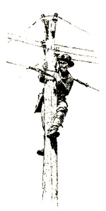 One of the key technologies from the civil war was the telegraph, both for transmitting military orders and for control of the railroad. I had hoped to add a telegraph system to my layout to add even more authenticity. There is another modeler across the river in Maryland that uses telegraphs for train orders and OS reporting on his layout. So it is a feasible aspect, but I know almost nothing about it.


