A journal following the history, design, construction and operation of Bernard Kempinski's O Scale model railroad depicting the U. S. Military Railroad (USMRR) Aquia-Falmouth line in 1863, and other model railroad projects.
©Bernard Kempinski All text and images, except as noted, on this blog are copyrighted by the author and may not be used without permission.
-----------------------------------------------------------------------------------------------------------------------------------------------------------------

October 30, 2012

Lee-Brooke Railway Gun

We made it through Hurricane Sandy with no damage. Our power flickered a few times, but it stayed on. Our sump pump was working nearly continuously and it did its job. We have battery back-up on the pump, but I am thinking a generator might be a good investment. Without that pump, the basement and layout would flood.

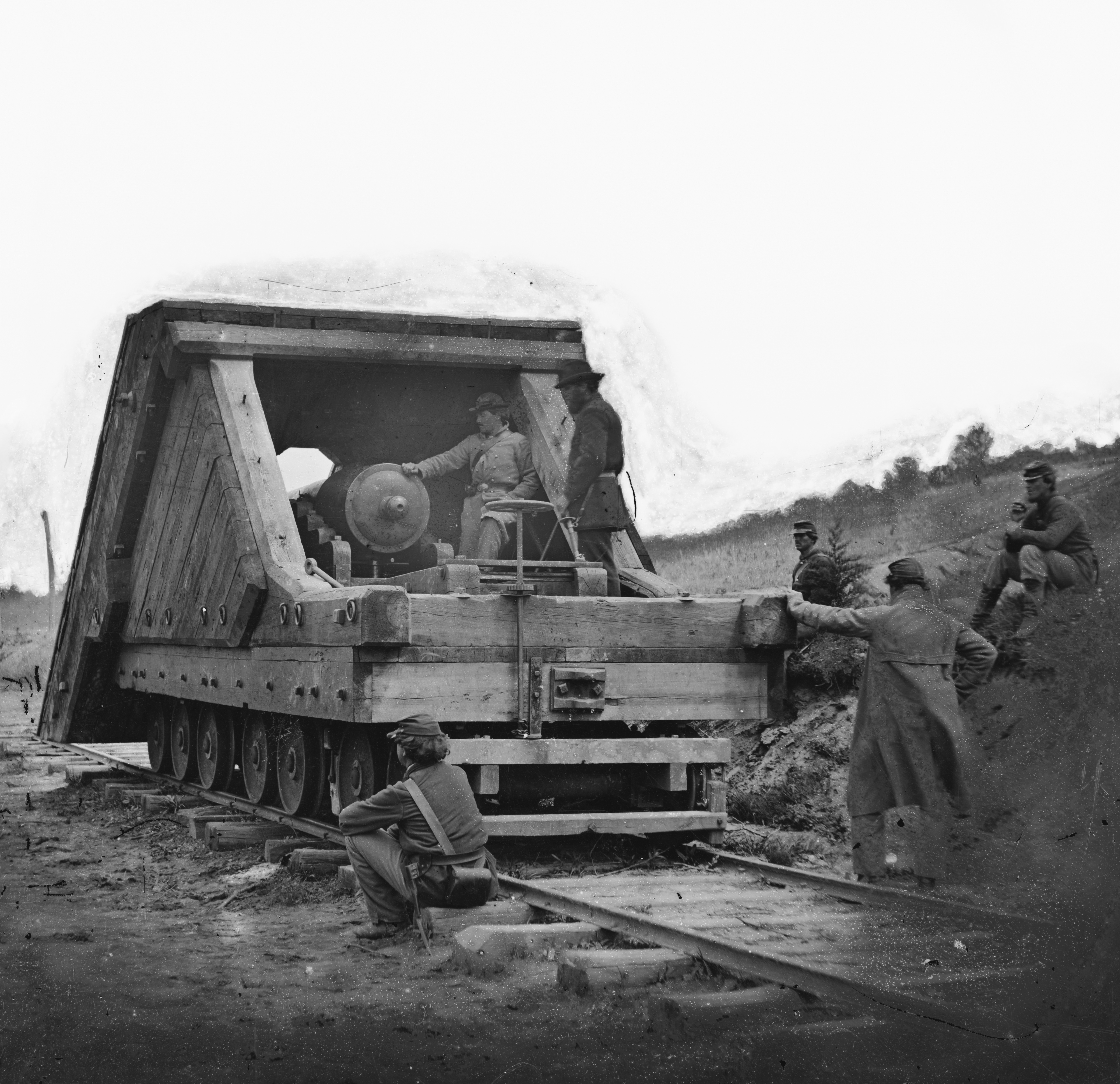
The Lee-Brooke Railway Gun. The LoC has a high resolution
 copy of this image.

Since I don't have enough to do, I added some more projects to my do list. The first is a model of the Lee-Brooke Railway Gun in 1:32 scale to match the Dictator mortar model I had made previously.  These two models will be on display at the B&O Railroad Museum next year. The Dictator is done, but the Lee-Brooke Gun has to be finished in a few weeks.

I plan to document the Lee-Brooke Gun construction in more detail in my book, but I posted some in-progress shots here. This is a tricky project as only two photos exist of this gun and many details are not visible. Dr Dave Schneider, of SMR Trains, did a good job of researching the gun and some of its construction details, but there are still many unanswered questions.

I was able to get good measurements of an existing rifled and banded Brooke 32 pound 57 cwt cannon at the Navy Yard in Washington.   I machined the model gun from brass rods. The main tube, trunnions and knob are separate pieces. Being brass they were easy to solder using my torch.

Using the gun dimensions and the rail gauge visible in the photo, I was able to scale most of the other dimensions of the model from the photos.

Brass cannon
I concluded that the plans in Alexander's book, while very good for overall proportion are off by about 50 percent. He assumed that the wheels are 33 inch wheels. But they are smaller, probably closer to 26-28 inches. I used 42 inch O scale wheels from NWSL (thanks are due to Derrel and Linda at NWSL for the rush job in shipping the wheels to me.) These scale out to 28 inches in 1:32nd scale.

I machined axles out of iron rods. The trucks are laser cut wood and plastic. I used photo etched brake parts from my O scale cars to fabricate the brakes for the rear truck.

Trucks and frame before decking.

I decided to make all the wheels on pivoting trucks based on the truss rod patterns on the side frames. They indicated to me that the front truck was similar to the rear two trucks. It is moot since in normal viewing, you really can't see the trucks. I also added the truss rods on the frame even though they are not visible from above.

It should be noted that this car has no evidence of longitudinal truss rods. I suspect that the lengthwise planks  as well as the heavy wood framing for the ironclad casement also serve as the the longitudinal stiffeners. I originally added longitudinal frame blocking, but removed them after reconsidering the location of the truss rods. I probably should have added two lengthwise beams and used transverse blocking. Oh well. I will change that the next time I do it, maybe in O Scale.

The gun carriage was really a dilemma, as I could find no other cannon with a carriage like this one. It looks to me that they took a seacoast casement  carriage from a fortress and modified it to fit. It appears to be a cross between the casement carriage (Plate 10 US Army Ordnance manual) and the carriage for flank  casements (Plate 11 US Ordnance manual). But many of the visible details don't match either of those guns. The number of steps on the side walls, the screw elevation and the type of gun are different. The Plate 10 carriage is close but there is no tongue on this gun, and the wheel tracks on the rails are different. In fact, the wheel tracks are not visible in the Lee-Brooke Railway Gun photo, but I assumed they are there and hidden by the view angle of the photo.

Gun and carriage sitting on chassis. The casement is
started.
So the approach I took was to copy all the detail that I could see and then did a little imagineering for the rest.  Based on the angle that the carriage rails sit on, I suspect it may have some type of pintle giving it a limited traverse.  I plan on adding that feature.

Given the dearth of information, any suggestions would be appreciated.


October 28, 2012

Meanwhile, back on the layout...

Hurricane Sandy is bearing down on the Mid-Atlantic and we are all standing by hoping it will spare us. With our storm preparations complete, I thought I would do a blog post to catch up some loose ends.


Last month I did a quick scratch build of a simple cook house for the tavern scene. The idea for the cook house came from some books I borrowed from Gerry Fitzgerald about vernacular architecture. In particular the book, Back of the Big House: The Architecture of Plantation Slavery (Fred W. Morrison Series in Southern Studies) was very handy. I based my building on a similar structure from this book. This building houses a kitchen and servants quarters. The servants were likely slaves before the Union Army arrived. The building is now being used by the Army as a kitchen and Quartermaster office.

I used Tichy windows and scribed siding. The roof shingles are laser cut red cedar with self-stick adhesive. The chimney is a simple scratchbuild from sheets of brick paper over a wood core. Due to the steep hillside, I had to install the building on wooden pilings.
The cook house uphill from the tavern

To complete the tavern scene I will also add a well house, cold cellar, hitching post and other details. I started adding some fencing, but more of these will be required. I also need to paint the backdrop in this area.

Edwin Alexander's figures
A photo from Alexander's book showing some of these
figures on his layout.
Yesterday I received in the mail and package from John Brazaitis containing 6 O scale figures. He purchased these figures from Edwin Alexander near forty years ago.

This is a real treat for me, because about 20 years ago I purchased a copy of Alexander's book, "Civil War Railroads and Models." I saw it on the discount table at Crown Books (now defunct) and purchased it.  Since then I  have studied and examined this book endless times so that the binding is worn out and the pages are coming loose.  In large part it was my inspiration to try some Civil War Railroad modeling. So I am very grateful to John for sending me these figures. I look forward to painting them and adding them to a prominent place on the layout.

Lets hope we have a home and layout to come back to after the storm passes over.


October 27, 2012

Exploring Expansion

The Road Show project is well under way, but I took some time tonight to flesh out some ideas that I had been thinking about for several months. I was motivated by the fact that the Road Show is currently occupying the same area that these expansion ideas would. Thus the Road Show demonstrates the feasibility of a layout expansion in this foot print.

I drew up two plans, one focusing on Alexandria and a second that expands the Aquia Landing area. I did not draw up the third plan I mentioned in the previous post as it would involve ripping out the current Falmouth section. That section is operating well, even with the tight turn back curve. So there is no burning need to replace it.

Extend Burnside Wharf

Alexandria
Of these two plans, I seem to favor the extended Burnside Wharf. I like the simplicity and  uncrowded look. I also like how it allows me to make the wharf at Aquia Landing bigger and closer to the actual wharf in appearance.

As much as I like Alexandria, that plan just seems too crowded to me. Although it  is more complicated than the Expanded Burnside Wharf plan, it would still only add one operating position to the layout. It might be possible to have two crews work Alexandria, but I think they would get in each others' way. 

I will be thinking about this as work on the Road Show and other projects progresses. No decision is needed just yet.


October 25, 2012

It is lit and fits!

Even temporarily clamped up the LED Light strips do a good job illuminating the layout.
I did some furniture rearranging in the basement and made room for the ACWRR Road Show to fit along the back wall. This includes all five sections. Having all the sections set up will make the track laying and valance fitting easier.

This also confirms in my mind that if I want to expand my USMRR Aquia Line layout, the perimeter wall around the basement can be used with relatively little intrusion into the TV viewing area. My long term plan is to build custom bookshelves along these walls. The book shelves would house the AV equipment as well as have storage space for media, books and some glass encased areas for displaying models. The shelves would have a flat space about 48 inches off the floor that would used for future layout projects. Whether it will be an expansion of the current layout or a completely new project I haven't decided.  Three possible expansions of this layout include extending the Burnside wharf to this area, adding a completely separate scene depicting Alexandria and connected by car float, or expanding the layout under the starirs and relocating Falmouth to this space. Or building a completely unrelated layout. Two themes that are possibilities are a steam era steel mill or a layout depicting the Alexandria waterfront and shipyard in WWI.

Virginia Shipbuilding Co in WWI

The whole layout fits along the back
wall of the basement.
But back to the road show, I took delivery of the LED strips yesterday. I tried some low current power supplies I had on hand and they did not do a good job of lighting the LEDs. So I hooked up the higher rated power supply that I ordered along with the LEDs. That required me to fabricate a 110V power cord. I had one on hand so it was a simple matter to hook it up by adding some spade connectors. With this power supply providing 12V and sufficient current, the LEDs are brightly lit. By using two strips of LEDs the layout should be well lit. The LEDs weigh next to nothing. They come with ballast resistors installed, so hooking them up is a snap.


Thinner and slightly lower valance panels

I also tried using a thinner valance panel and lowered it so that the top was flush with the valance frames. I think this look better and will make adding a top panel easier if we decide to do that. The thinner lower valance creates an opening 14 inches from water surface to valance bottom. It will make the sections a little less bulky.  I think it creates a more finished product, as the valance won't protrude like a false front in this configuration.


October 22, 2012

A section too far?

Bill Mosteller, proprietor of Great Decals, stopped by to see the layout tonight. After a quick tour and running a train around the layout, he offered to help move the Road Show to the basement. With his and AW's help we got all the sections and tools moved to the basement. The garage is  cleared up so the car can fit back in there.

Three sections is all I can set up at one time in my basement. Anybody want a layout section?
A couple observations on moving the layout. The sections are fairly light, but they are bulky, especially the bigger ones.

The valance supports are just too tempting to use as handles.  I need to  beef them up so that they can  act as handles if necessary. The legs will need some type of locking mechanism for both the down and up positions.  There may be an existing table leg hardware solution we can modify. Bill mentioned that he was impressed with the folding legs but agreed that a locking device was needed.